1. Introduction - Machine Overview
10 Morgana DocuMaster MFC - Service Manual
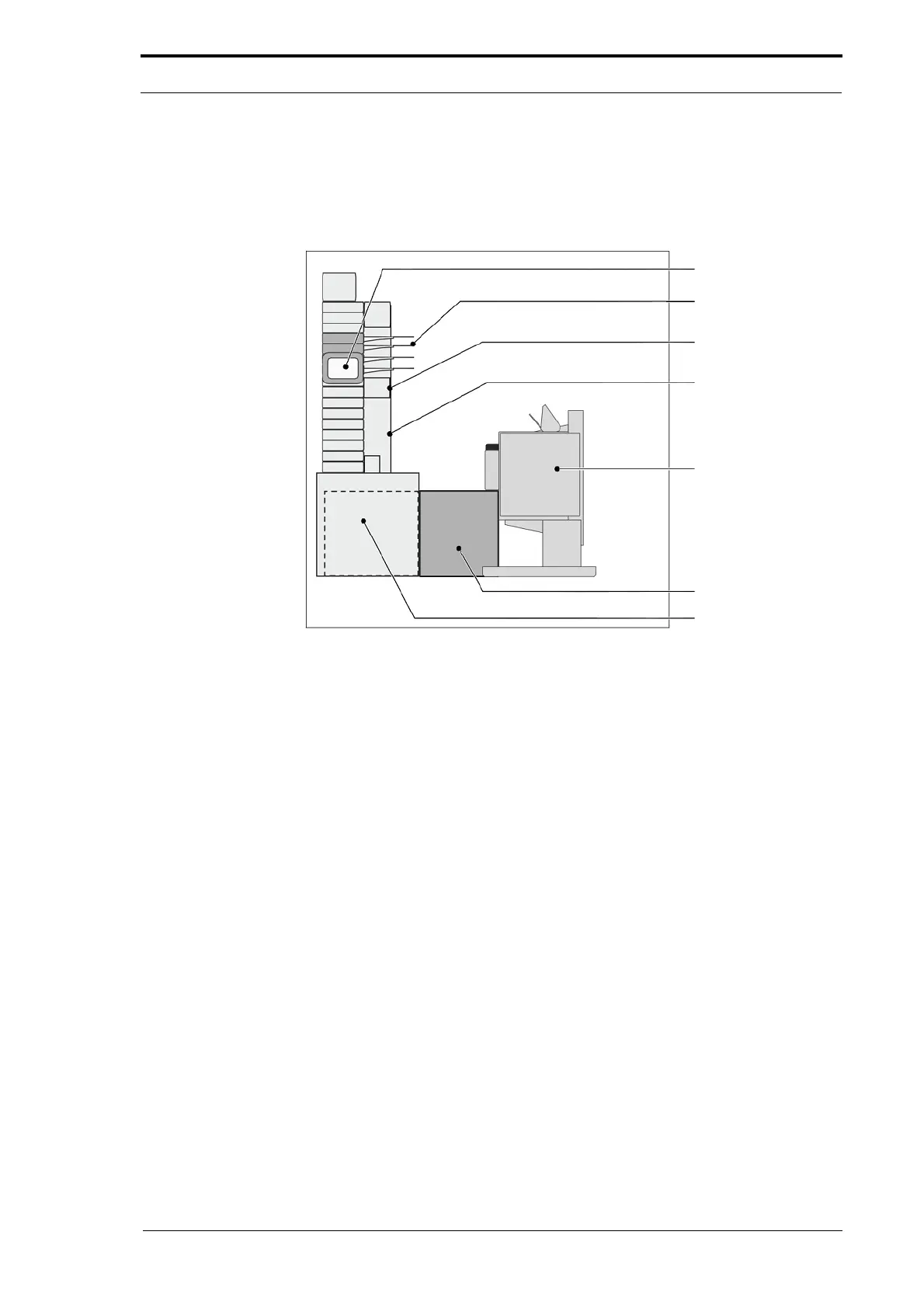
1.8 Machine Overview
The MFC has a modular construction that makes it easy to disassemble for servicing
and maintenance.
3. GUI Panel
4. Feed Bin
5. Creaser Module
6. Gathering Area
SquareBack
Trimmer
BookletMaker
Figure 1.5 DocuMaster MFC with Online Booklet Maker and SquareBack System
1. The CAP (Combined Air Pump): The CAP module includes the blower and the vacuum
motors in an enclosed acoustically-insulated box. The internal temperature of the CAP is
controlled by forced-air cooling operated by a thermostat sensor. The cooling fan will continue
to operate after the MFC has stopped until the internal temperature is below 50°C.
2. The DRV (Drive Unit):
The DRV module includes the main drive motor and
electronics necessary to control the MFC feed system. It also includes the high voltage
anti-static transformer that operates the ioniser bar in the sheet gathering area.
The components in the DRV are the:
• main drive motor
• feeder and touchscreen CPU
• blower motor control PCB
• interface PCB
• low-voltage transformer
• high-voltage anti-static transformer
• mains inlet plug
• mains input ON/OFF switch
• emergency stop switch
• air filter.
The DRV module has three access doors that can be
opened by an engineer for
service and maintenance.