4. Service Procedures - Diagnostic Procedures
56 Morgana DocuMaster MFC - Service Manual
4.4.2.3 Test the Ioniser Bar
The ioniser bar must generate an electrical field
through a 180° arc, 120mm from the
emitter side of the bar and along its entire length. Use a non-contact volt sensor to test
the electrical field.
Before you start:
• Make sure that the ioniser bar is clean (See Section 4.13.5).
Step Action Information
1 Turn on the MFC.
2 Do a check that the ioniser bar
emit
s a low electrical buzz.
If the ioniser bar does not buzz and
the transformer is good, the ioniser
bar is defective and must be replaced
(see Section 4.11.4).
3 Hold the volt sensor between the
emitter side o
f the ioniser bar and
the back panel of the gathering
area.
• If no output is shown replace the
ioniser bar (see Section 4.11.4).
• If a weak output is indicated
(50mm or below) replace the
ioniser bar (see Section 4.11.4).
• If the output shown is not equal
(stronger at one end than the
other) replace the ioniser bar
(see Section 4.11.4).
4 Use a high voltage probe (1000 to
1) to
measure the voltage across
the pins of the ioniser bar.
The voltage across the pins should
be approximately 6.5kV.
If the voltage measured is below
4.0kV replace the
ioniser bar (see
Section 4.11.4).
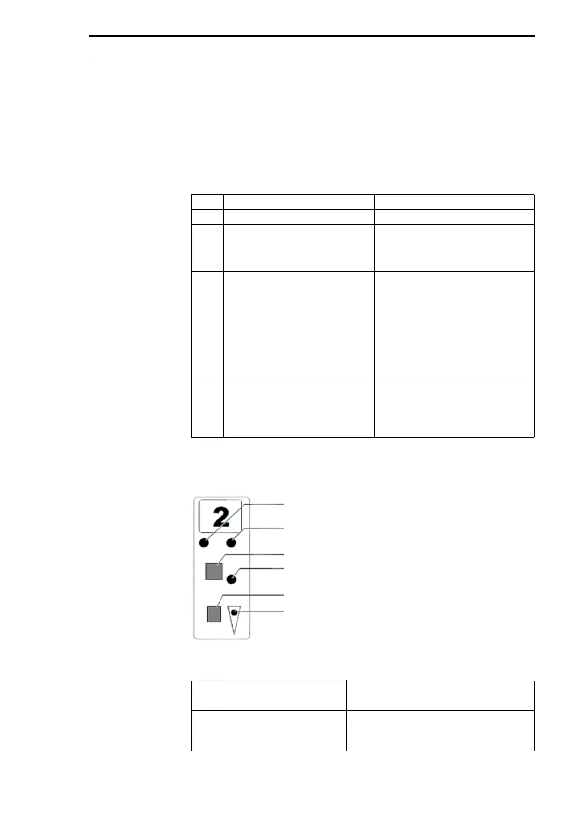
4.4.3 Test a Feed Bin Emitter/Sensor Assembly
Figure 4.22 Feed Bin Control Switch
Item Description Function
1 Red light Shows a double feed (less light received).
2 Yellow Light Shows a miss feed (more light received).
1 & 2 Red and Yellow lights Shows a trailing or jam error (shows low
range set in '
Test Mode').