1. Introduction - Description of Operation
16 Morgana DocuMaster MFC - Service Manual
The emitter/sensor senses again 30mm after the check for trailing errors. The final
sensor check is for jam errors, which are caused when a sheet is trailing very badly or
if a sheet has physically jammed when it fed. If a trailing or jam error is detected, the
MFC will stop.
The Friction Bin Feed Sequence: The friction bin feed sequence is identical
to the
suction feed sequence. However, the friction feed bin does not have a blow valve or
vacuum valve.
1.9.3 The Creaser
The creaser rollers are driven by a DC stepper-motor in the creaser module. The
creaser roller drive-motor operation is synchronised to the MFC conveyor-drive motor
by the creaser control PCB and the master timing PWM (Pulse-Width Modulation)
signal. This is important because both the MFC conveyor and the creaser drive rollers
must stop when the paper is creased.
When a sheet of paper enters the creaser module it
moves through an array of edge-
sensors that are positioned across the width of the conveyor. The MFC will use only
two pairs of sensors at a time. Which sensors are used is set by the sheet width value
entered by the user on the GUI panel.
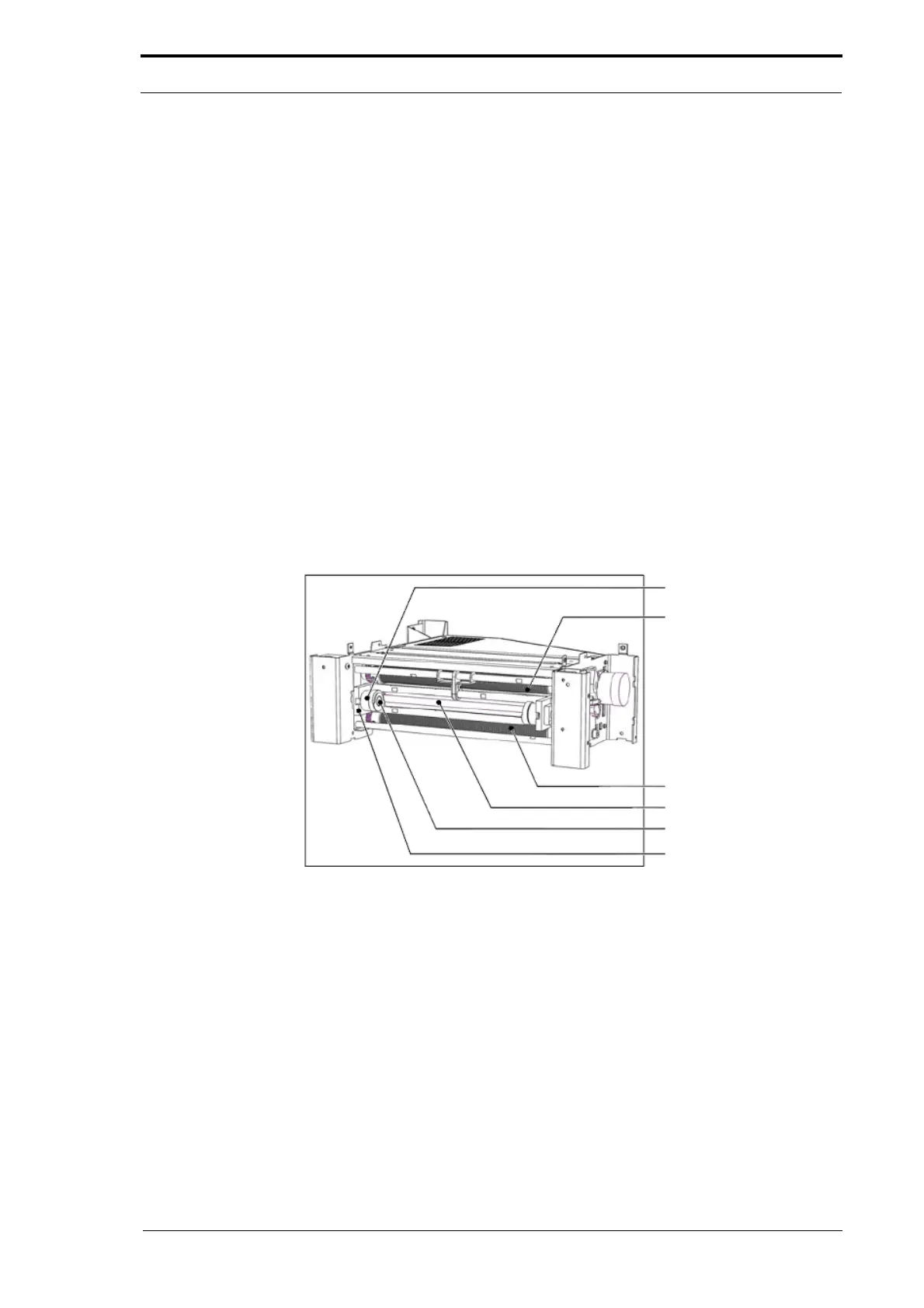
Pressure Adjuster
Input Rollers
Output Rollers
Creaser Blade-Set
Locking Bolt
DynaTilt Side Frame
Figure 1.7 The Creaser Module
The edge-sensors detect the skew of each sheet (how far from parallel the front edge
of the sheet is from the sensor-set). The creaser control PCB calculates the angle that
the DynaTilt mechanism must set the creaser unit to. This calculation is made using
three known values:
• The calibrated ‘0’ (parallel) position
• The current skew angle of the DynaTilt mechanism
• The skew angle of the sheet.
The DynaTilt mechanism is adjusted by a 24V stepper-motor
. The mechanism is
calibrated to a home position switch when the creaser module is first turned on or
started.