Morgana DocuMaster MFC - Service Manual 15
1. Introduction - Description of Operation
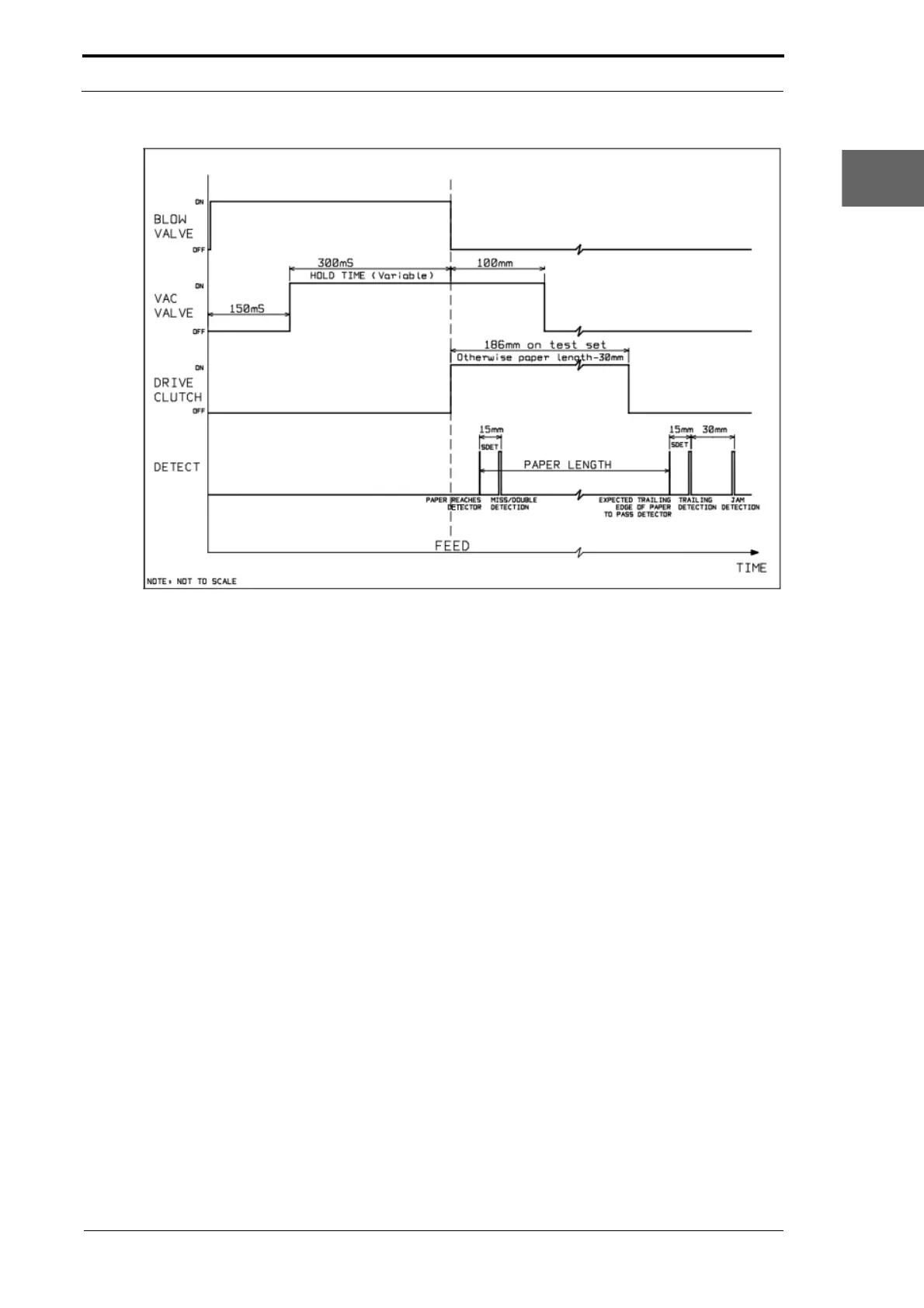
Figure 1.6 The Suction Feed Bin Paper Feed Sequence Diagram
The Suction Bin Feed Sequence: When the feed sequence starts the timed air
separation is turned on. A solenoid controlled diaphragm valve, which is connected to
the MFC separation air supply, is opened to give a blast of air into the paper stack. The
blow valve is open for 150mS before the vacuum valve opens and it stays open until
the feed clutch is turned on (see Figure 1.6). This is necessary to lift the top sheet
towards the feeder.
The vacuum valve is open for a default of 300mS
before the feed clutch is turned on.
This gives enough time for a sheet of paper to be held tight against the feed belt.
When the feed clutch is turned on, the vacuum valve st
ays open until the sheet has
been fed 100mm into the conveyor nip. The vacuum valve is turned off and it releases
the sheet into the conveyor. The feed clutch engages drive to the feeder belt, and stays
on for the entire sheet length, -30mm, which stops pre-feed of the sheet below it.
When the front edge of the sheet is calculated to
have moved past the emitter/sensor
by 15.2mm, the feed bin senses for a miss or double error. If a miss or double error is
sensed, the feed bin control PCB will send an error signal to the MFC CPU. The CPU
buffers this error and will stop the MFC with the sheet in the gathering area and show
the type of error on the GUI panel and bin control switch.
The emitter/sensor is then used again to detect that the sheet has lef
t the bin. It senses
first for trailing errors, which are caused when a sheet is late to feed, or if a second
sheet is fed behind the first. The sensor check for trailing errors is made the same
distance after the back edge of the sheet as the sensor detection setting (SDET). The
default SDET value is 15.2mm, so by default, the sensor check for a trailing error
occurs 15.2mm after the calculated back edge of the sheet. If the SDET value is
adjusted, the sensor check for trailing errors will automatically change.