June 11, 2003 6881096C73-O
9-2 Basic Troubleshooting: Introduction
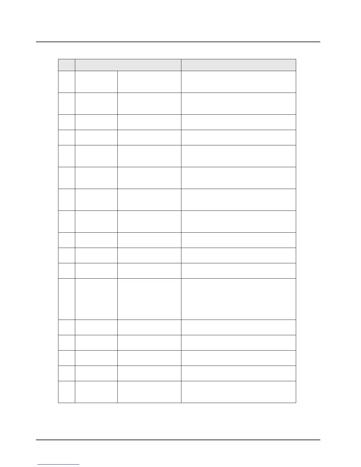
4 TXD RS232 Transmit Data This is part of the 4-wire RS232 interface to
external data accessories, programming
cables, etc.
5 RXD RS232 Receive Data This is part of the 4-wire RS232 interface to
external data accessories, programming
cables, etc.
6 USB- USB - Data This is part of the 2-wire USB differential data
bus for future USB accessories.
7 USB+ USB + Data This is part of the 2-wire USB differential data
bus for future USB accessories.
8 RESET SB9600 RESET This is part of the Motorola SB9600
communications bus to connect external
devices.
9 BUSY SB9600 BUSY This is part of the Motorola SB9600
communications bus to connect external
devices.
10 CTS RS232 Clear-To-Send This is part of the 4-wire RS232 interface to
external data accessories, programming
cables, etc.
11 RTS RS232 Request-To-
Send
This is part of the 4-wire RS232 interface to
external data accessories, programming
cables, etc.
12 USB PWR USB Power This is the supply (5V) for the USB data bus,
supplied by the USB accessory/cable.
13 CHAN ACT Channel Activity This is an output used for indicating detection/
unsquelching of a qualified received signal.
14 GROUND Ground Used as a ground for any reference on rear
connector.
15 EMERGENCY Emergency This pin must be connected to ground by
jumper on accessory cable if emergency is
disabled, even if disabled by CPS. If enabled,
this line must be grounded via a switch, which
is normally closed. The emergency debounce
time is programmable via CPS.
16 PTT* Push To Talk Pulling this line to ground will activate PTT
function, activating the AUX_MIC input.
17 ONE WIRE One-Wire data To be used for identification of future smart
accessories/cables.
18 VIP OUT 1 Vehicular Interface
Output
High voltage output used for enabling relays
used for accessories such as horn/lights.
19 VIP OUT 2 Vehicular Interface
Output
High voltage output used for enabling relays
used for accessories such as horn/lights.
20 SPKR+ Speaker + Used along with SPKR- to connect an external
speaker. The audio PA is a bridge amplifier
with a 3.2-ohm minimum impedance.
Table 9-1. J2 Accessory Connector Signal and Voltage Descriptions (Continued)
Pin Function Description

 Loading...


