June 13, 2003 6881096C73-O
8-2 Disassembly/Reassembly Procedures: Replacement Procedures
8.2.2 Control Head Boards Disassembly/Reassembly
8.2.2.1 W3 Disassembly
NOTE: Bracketed numbers are identical to item numbers shown in Figure 11-1. “W3 Hand-Held
Control Head Exploded View” on page 11-2.
1. Remove the strain-relief boot covering the control-head cable connector [15] from the
housing assembly [7] by pulling it away from the control head until they are completely
separated.
2. Carefully remove the rubber seal (part of cable assembly [15]) from the housing assembly [7]
opening.
NOTE:Take care to avoid damaging this seal.
3. Using a small screwdriver, remove the seal support wedge [14] from the control head.
4. Using a small screwdriver to depress the telco lever, remove the telco connector at the end of
the cable assembly [15] from the control head, and pull the cable assembly away from the
housing (like a telephone jack).
5. Remove the rear cover assembly [2] from the control head.
Locate the recesses in the lower portion of the housing on both sides of the rear cover’s snap
features and, prying the snaps until the two parts separate, remove the rear cover from the
unit.
6. Remove the two snap retainers [4] from between the SB9600 circuit board [5] and the
housing assembly [7].
7. Disconnect the microphone assembly [8] connector from the SB9600 circuit board [5].
8. Carefully remove the microphone assembly [8] from the keypad [6].
NOTE:Be careful to avoid damaging circuit-board components in the next step.
9. There are seven snaps locking the circuit board to the housing. Carefully pry the housing’s
snap features from the SB9600 circuit board [5]. As the snap features are deflected, push the
circuit board upward, using the keypad, to release the circuit board from the snap features.
10. Remove the circuit board assembly from the housing assembly [7].
11. Remove the keypad [6] from the housing assembly [7].
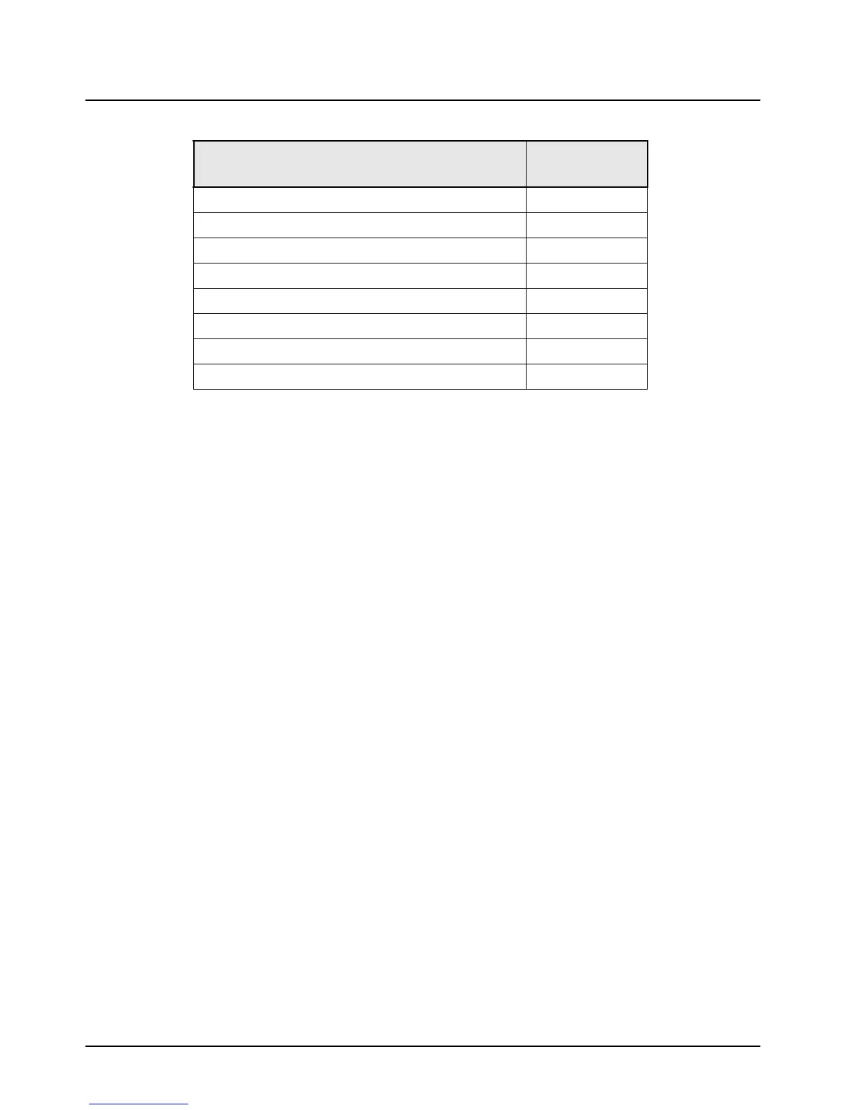
Magnetic screwdriver set with bits 0180320B16
Mini-UHF to N-type adapter cable 3085651A01
Plastic scraping tool 6686119B01
Removal and insertion tool 6680163F01
Roto-Torq adjustable driver RSX4043
Small, flat-blade screwdriver
Solder aid (black stick), Hexacon Electric Co. MA-800G
Torx® T10 and T20 drivers
Table 8-1. Required Tools and Supplies (Continued)
Tools and Supplies
Motorola
Part Number

 Loading...


