June 11, 2003 6881096C73-O
9-8 Basic Troubleshooting: Receiver Troubleshooting
NOTE: “AC-coupled” is adding a 10 µf capacitor externally to prevent biasing on the MIC-HI line from
being grounded.
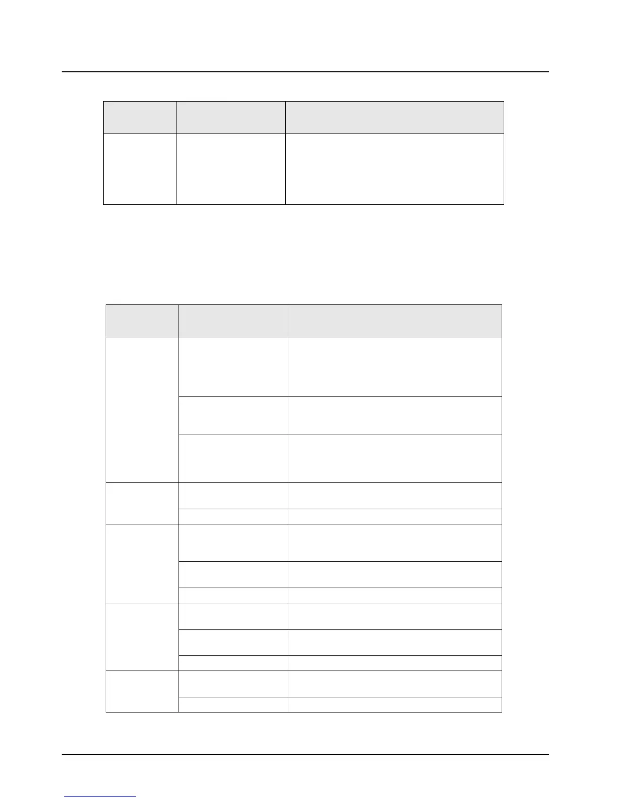
9.6 Receiver Troubleshooting
Table 9-6 can help you troubleshoot problems that might occur in the receiver section of your radio.
Radio
transmiits when
programming
cable is
inserted into
control head
Damaged Flex Replace flex to control head.
Table 9-6. Receiver Troubleshooting Chart
Symptom Possible Cause
Correction or Test (Measurements Taken
at Room Temperature)
Radio Dead,
Display Does
Not Light Up
Blown Fuse Check the current if drain is >800 ma or if the
current is <400 ma, refer to the Detailed Service
Manual for mainboard repair.
Check the fuse in the red lead of power cable (or
green lead if used.)
Main Board Check for ignition at J0401-20 and at J0401-19 and
21 (both >10 Vdc). If not present, refer to the
Detailed Service Manual.
On/Off Switch (Control
Head)
Check for SW_B+ at pin 17 of J0401 on the main
board.
If present, replace flex or remote cable and board.
If absent, replace control head.
Radio Dead,
Display Lights
Up
Flex Circuit Check for SW_B+ at pin 17 of J0401.
If absent, replace the flex or remote cable/board.
Main Board Refer to the Detailed Service Manual.
No Receiver
Audio or
Receive Does
Not Unsquelch
Code Plug Check the codeplug to ensure correct frequency
and signaling (PL, DPL) is enabled (use the
appropriate radio-programming software).
Speaker Check for speaker leads shorted to ground or open
speaker wires. Replace, if necessary.
Main Board Refer to the Detailed Service Manual.
Audio Distorted
or Not Loud
Enough
Codeplug Ensure the codeplug is properly configured,
including bandwidth and signaling.
Synthesizer Not On
Frequency/Working
See “Reference Oscillator Alignment” on page 6-6.
Main Board Refer to the Detailed Service Manual.
RF Sensitivity
Poor
Synthesizer Not On
Frequency/Working
Check the local oscillator frequency.
See “Reference Oscillator Alignment” on page 6-6.
Main Board Refer to the Detailed Service Manual.
Table 9-5. Transmitter Troubleshooting Chart (Continued)
Symptom Possible Cause
Correction or Test (Measurements Taken at
Room Temperature)

 Loading...


