Functional Block Diagrams and Connectors: Radio Connector Locations 10-4
6881096C73-O June 12, 2003
10.3 Radio Connector Locations
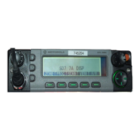
Figure 10-8. Dash-Mount Radio Connector Locations
Figure 10-9. Remote-Mount Radio Connector Locations
10.4 Radio Connector Locations (cont.)
Figure 10-10. Main Board Connector Locations - Side 1
Figure 10-11. Main Board Connector Locations - Side 2
MAEPF-27645-A
0
P
W
R
M
ode
Scan
Phon
Sel
C
all
Vol
D
IM
H
O
M
E
X
M
IT
B
U
S
Y
1
2
3
4
5
6
7
8
9
0
S
t
s
M
s
g
H
/
L
M
o
n
D
ir
R
c
l
D
e
l
P104
Antenna
DC
Power
J2
REAR
VIEW
MAEPF-27644-A
0
P
W
R
Mode
Scan
Phon
Sel
Call
Vol
DIM
HOME
XMIT
BUSY
1
2
3
4
5
6
7
8
9
0
Sts
M
sg
H/L
M
on
Dir
Rcl
Del
P104
J0103
J5
J6
Antenna
DC
Power
J2
REAR
VIEW
J0950
J6700
J0402
FRONT EDGE OF BOARD
31
322
1
MAEPF-27663-O
J0950
J6700
J0501
J0401
FRONT EDGE OF BOARD
2
2
1
2
20
1
50
49
19
1
231
MAEPF-27664-O

 Loading...


