June 11, 2003 6881096C73-O
8-4 Disassembly/Reassembly Procedures: Replacement Procedures
15. Push the rubber seal (part of the cable assembly [15]) into the housing’s opening and ensure
that it is properly seated.
NOTE:This seal must be inserted completely into the housing to ensure the rain seal.
16. Push the strain relief boot (part of the cable assembly [15]) into the housing, and ensure that
it is properly seated.
17. Insert the kit label [1] into the recess on the rear cover, ensuring that it is securely attached.
8.2.2.3 W4, W5, and W7 Disassembly
NOTE: For the following procedure, refer to Chapter 11. Exploded Views and Parts Lists, beginning
on page 11-1, for the exploded view and associated parts list applicable to the model being
disassembled.
1. Unplug the microphone.
2. Remove the two front panel screws using a 2.5 mm hex-key driver.
3. Disconnect the control cable on remote models.
4. Grasp the front panel firmly, and carefully unplug the control head assembly from the radio or
remote control head back housing. For dash-mount models, unplug the interconnect flex
cable from the control head.
5. Lay the control head face down on a clean, flat surface, being careful not to scratch or mar
the display.
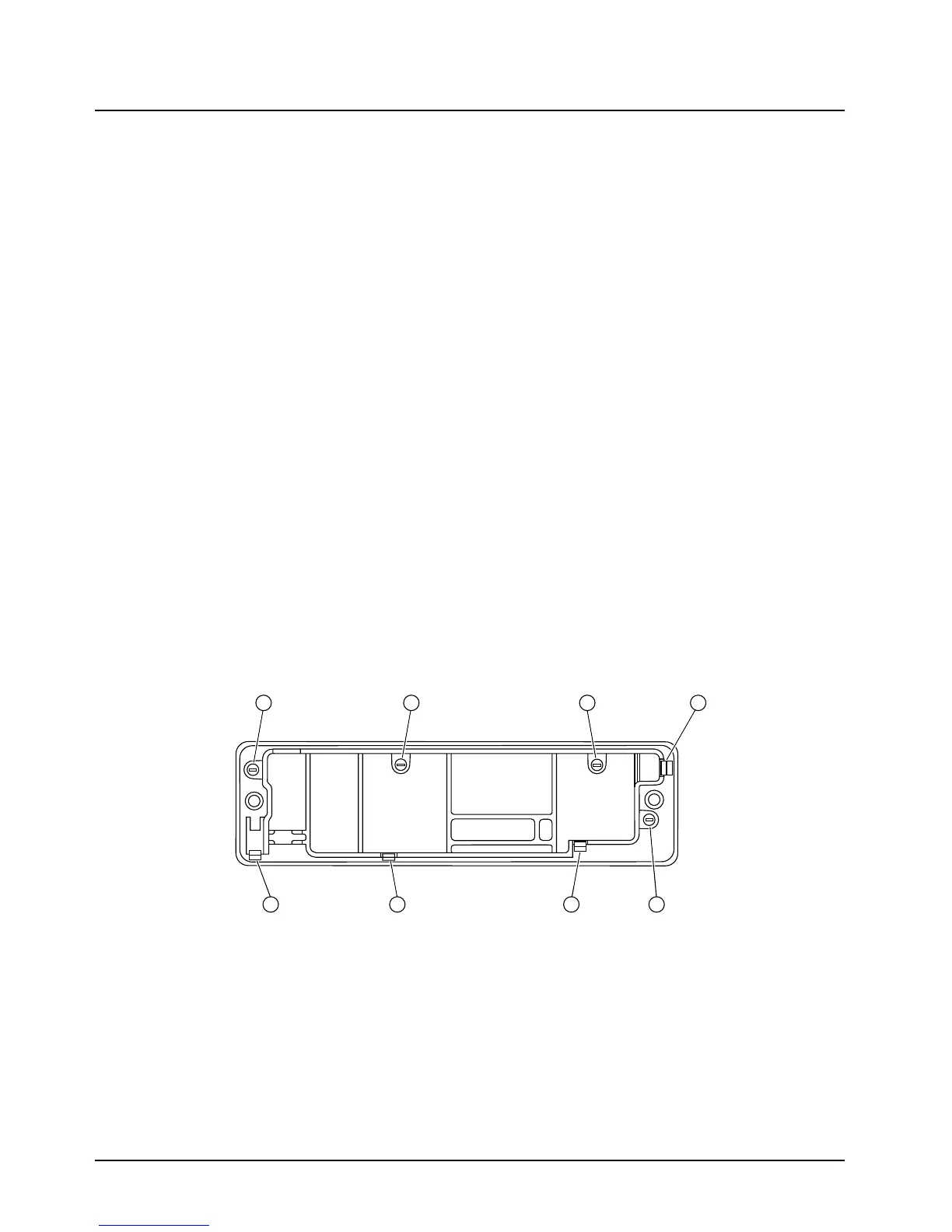
6. Using a Torx T10 driver, remove the control head screws:
- W4 control head: four screws [callouts 5-8], as shown in Figure 8-1 on page 8-4.
The W4 control head has, in addition to the screws, four snap features [callouts 1-4], which are
shown in Figure 8-1 on page 8-4.
- W5 and W7 control heads: seven screws, as shown in Figure 8-2 on page 8-5.
Figure 8-1. W4 Rotary Control-Head Assembly Screw and Snap Sequence
7 1
58
3
4
2 6

 Loading...


