June 11, 2003 6881096C73-O
6-6 Radio Alignment Procedures: Transmitter Alignments
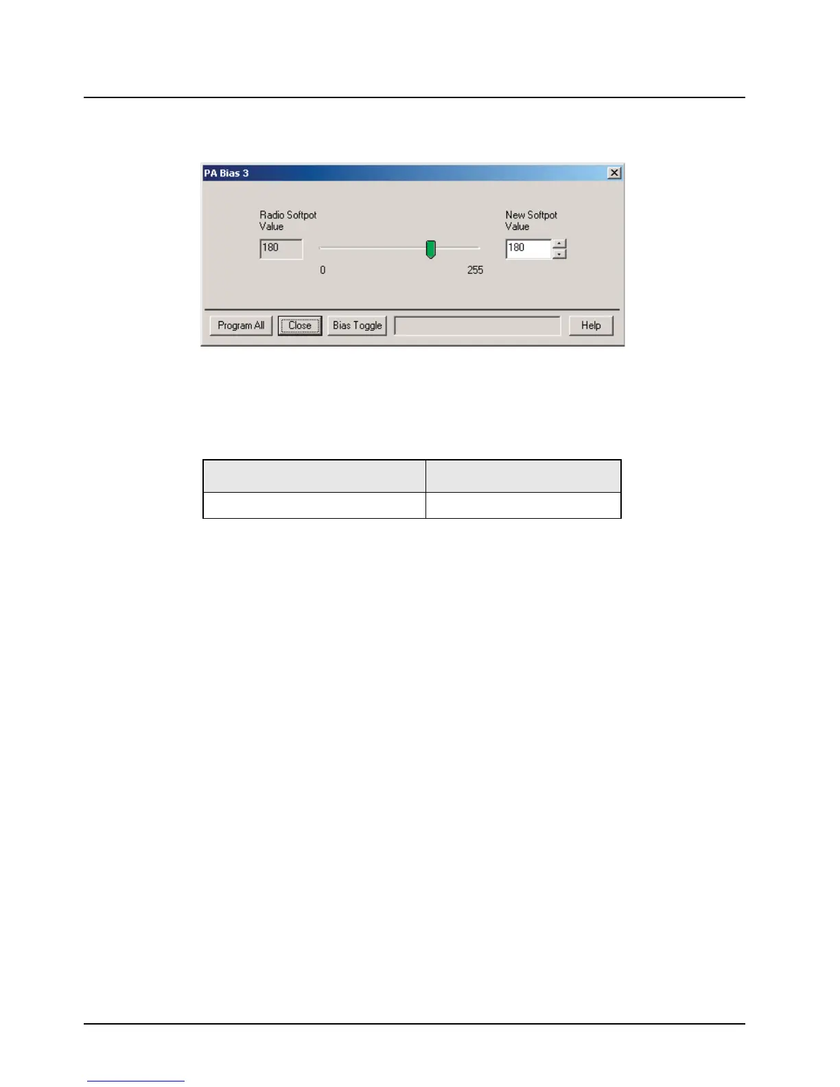
2. Select PA Bias 3 from the Tuner Main Menu. When the screen is opened, the radio enters a
special bias tune mode and radio current increases by approximately 100 mA.
Figure 6-6. PA Bias 3 Alignment Screen
3. Read baseline current from current meter on power supply.
4. Add baseline current to device bias current to calculate target current.
5. Left-click the Bias Toggle button to apply bias to gate of device.
6. Adjust softpot value until target current is achieved within
±10%
7. Left-click the Bias Toggle button to remove bias from gate of device.
8. Left-click the Program All button to save tuned value.
9. Left-click Close button to close the screen and return to the Tuner Main Menu.
6.4.4 Reference Oscillator Alignment
Radios are shipped from the factory with a worst-case frequency error of ±500 Hz for 700–800 MHz.
These specifications are tighter than the more stringent FCC requirements of ±1.5 ppm for the 700–
800 MHz bands.
For radios that have been in storage for over six months from the factory ship date, the reference
oscillator should be checked when the radio is initially deployed to the field. It is strongly
recommended that the reference oscillator be checked every time the radio is serviced or at least
once a year, whichever comes first.
The crystal contained in the reference oscillator naturally drifts over time due to its aging
characteristic. Periodic (annual) adjustment of the reference oscillator is important for proper radio
operation.
Improper adjustment can result in both poor performance and interference with other users operating
on adjacent channels.
Table 6-9. PA Bias 3 Alignment Device Bias Current
Band/Power Level Device bias current (mA)
700–800 MHz 35 W/15 W Motorcycle 100

 Loading...


