6881096C73-O June 11, 2003
Radio Alignment Procedures: Transmitter Alignments 6-9
6. Left-click the Program All button to save tuned value.
7. Left-click Close button to close screen and return to the Tuner Main Menu.
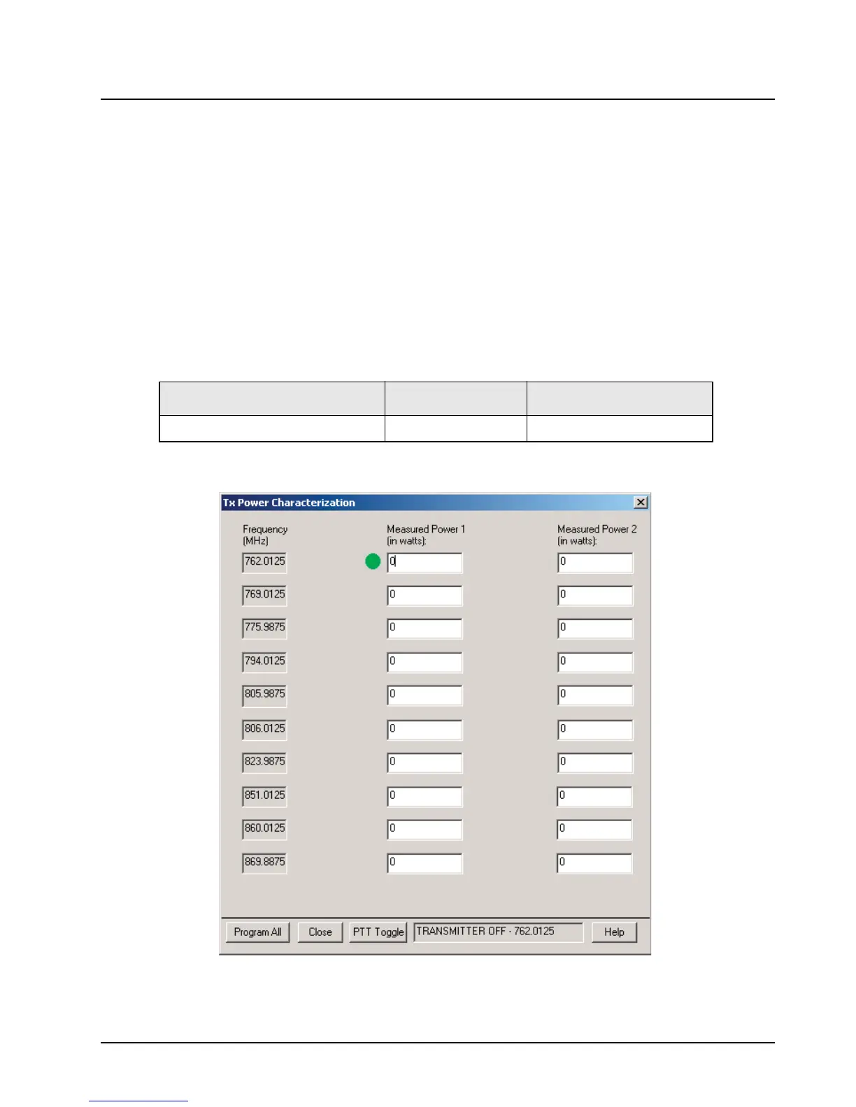
6.4.6 Tx Power Characterization
NOTE: This alignment is required after replacing (or servicing) the transceiver board.
The Tx Power Characterization alignment procedure characterizes power tuning so that Tx power
can be adjusted with CPS software. You will transmit at two power levels for each test frequency and
record the measured power level with 0.1 W resolution.
NOTE: The antenna port should be terminated with a calibrated power meter through a 30 db RF
pad.
1. Set the power supply voltage and current limit as indicated in Table 6-12.
2. Select Tx Power Characterization from the Tuner Main Menu.
Figure 6-9. Tx Power Characterization Alignment Screen
3. Left-click in the first box of the Measured Power 1 column. A green circle will appear to the
left of box indicating active characterization point.
Table 6-12. Power Supply Voltage Settings
Band/Power Level Supply Voltage (V) Supply Current Limit (A)
700–800 MHz 35 W/15 W Motorcycle 13.6 15

 Loading...


