June 11, 2003 6881096C73-O
6-8 Radio Alignment Procedures: Transmitter Alignments
5. Adjust the reference oscillator’s softpot value until the measured value is as close as possible
to the frequency shown on the screen. Allow approximately five seconds for the analyzer
frequency reading to stabilize after each change. See Table 6-10.
6. Left-click the Program All button on the screen to dekey the radio and save the tuned values.
7. Left-click the Close button on the screen to return to the Tuner Main Menu.
6.4.5 Power Detector Calibration
NOTE: This alignment is required after replacing (or servicing) the transceiver board.
The power detector calibration alignment procedure adjusts the buffer gain for the forward power
detector to minimize radio power variation from radio to radio.
NOTE: Antenna port should be terminated with calibrated power meter through a 30 db RF pad.
1. Set the power supply voltage and current limit as indicated in Table 6-11.
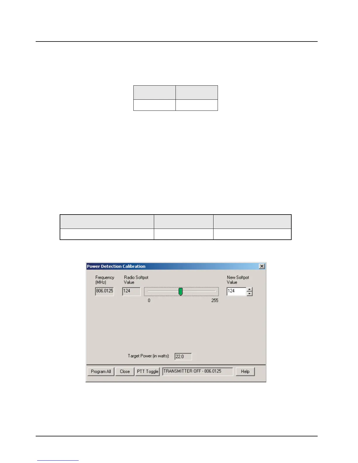
2. Select Power Detection Calibration from the Tuner Main Menu.
Figure 6-8. Power Detection Calibration Alignment Screen
3. Left-click the PTT Toggle button to transmit at indicated frequency.
4. Adjust softpot value until target power is achieved.
5. Left-click the PTT Toggle button to disable transmit mode.
Table 6-10. Reference Oscillator Alignment
Band Target
800 MHz ±100 Hz
Table 6-11. Power Supply Voltage Settings
Band/Power Level Supply Voltage (V) Supply Current Limit (A)
700–800 MHz 35 W/15 W Motorcycle 13.6 15

 Loading...


