6881096C73-O June 11, 2003
Radio Alignment Procedures: Transmitter Alignments 6-7
This test can be done with either the R-2670 Communication Analyzer or the Agilent 8901
Modulation Analyzer.
• Initial set up using the R-2670 Communication Analyzer:
- RF Control: MONITOR
- B/W: WB
- Freq: RSS frequency under test
- Attenuation: 20dB
- Mon RF in: RF I/O
- Meter: RF Display
- Mode: STD
- Input Level: uV or W
- Display: Bar Graphs
- Squelch: Mid-range or adjust as necessary
• Initial set up using the Agilent 8901 Modulation Analyzer:
- Press the green Automatic Operation button on the analyzer.
- Press the FREQ key.
- Type 7.1 followed by the SPCL button to set the 8901 Modulation Analyzer for maximum
accuracy.
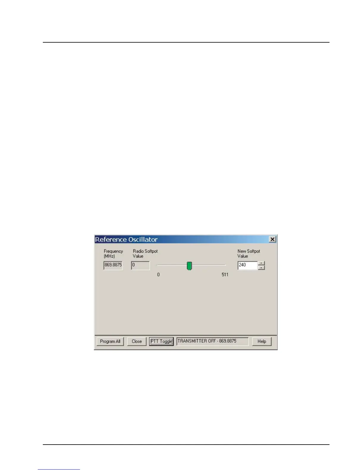
1. Select Reference Oscillator from the Tuner Main Menu (Figure 6-7).
Figure 6-7. Reference Oscillator Window
2. If you are using the R-2670 analyzer, enter the frequency displayed on the Tuner screen in
the "RF control" section of the R-2670. Under the "Meter" section of the display, choose
RF DISPLAY.
3. Left-click the PTT Toggle button on the screen to make the radio transmit. The screen
indicates whether the radio is transmitting.
4. Wait five seconds until the analyzer reading stabilizes, and then record the transmitter
frequency.

 Loading...


