Chapter 3 Basic Theory of Operation
3.1 Introduction
The ASTRO XTL 5000 radio combines the controller and RF sections into a single board and
contains three modules: a daughtercard, RX VCO module, and TX VCO module. It is important to
correctly identify the malfunctioning region before replacing expensive modules. To assist with radio
repair, descriptions of the sections contained on the XTL 5000 uniboard are listed below.
3.2 General Overview
The XTL 5000 radios are wideband, synthesized, fixed-tuned radios and are available with 700 and
800 MHz bands. All XTL 5000 radios are capable of both analog operation (12.5 kHz, 20 kHz, and
25 kHz bandwidths) and ASTRO mode operation (12.5 kHz bandwidth).
The XTL 5000 radios contain the following assemblies and sections:
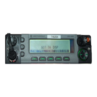
• Control-Head Assembly (Dash- or Remote-Mount)—is connected directly to the front of the
transceiver or remotely by the interconnect board and control cable. This assembly contains a
vacuum fluorescent (VF) display, VF driver, microprocessor and serial bus interface.
• Power Amplifier (PA) section—contains the antenna switch, directional coupler/ detector, and
amplifier(s).
• Front-End Receiver section—contains the preselector, low-noise amplifier (LNA), and mixer.
• IF section—contains the receiver intermediate-frequency (IF) amplifier/filter and the digital
receiver back-end integrated circuit (IC).
• Frequency Generation section—contains the synthesizer, voltage controlled oscillators (VCOs),
reference oscillator, and receive and transmit buffers.
• Controller section—combines a VOCON board and a Command board, into a single section,
and contains the following elements:
- Voltage regulators, data communication circuitry (RS232, USB, and SB9600)
- Daughtercard module (Microprocessor, FLASH IC, SRAM IC)
- Modulation D/A conversion circuitry
- CODEC audio circuitry
- TX power-control circuitry
- Emergency circuitry
- V.I.P input/output paths
- Secure interconnect board interface
- Front connector interface for control heads and remote-mount interconnect boards (I.B)
- Rear connector for additional accessories
- DC power-in plug

 Loading...


