Functional Block Diagrams and Connectors: Control Head Connector 10-6
6881096C73-O June 12, 2003
10.6 Control Head Connector
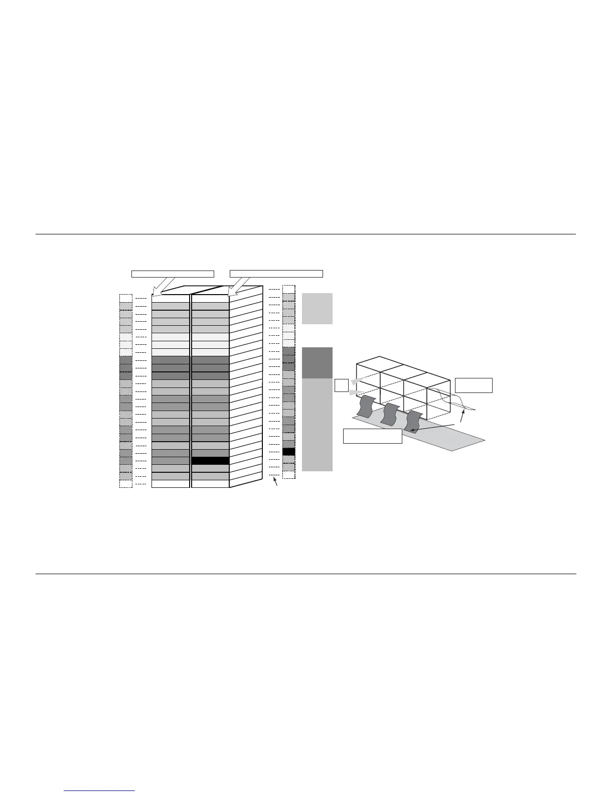
Figure 10-13 illustrates the pin arrangement and associated signals and voltages for the 50-pin control-head connector.
Figure 10-13. Control Head 50-pin Connector
GND
Mic Hi
Aux Mic
Aux Rx
Spk-
VIP OUT 2 - 12V
VIP OUT 2 - 5 V
VIP IN 2 - 5V
emerg.
IGN
Opt B+
One Wire
Boot RX
UARTA-RX
UARTA-RTS
Bus-
LH_Reset
SAP-RX
SAP-Fsync
Naut-INT
SPI-miso
SPI-clk
BUS_PWR_OUT
TBD
GND
2
4
6
8
10
12
14
16
18
20
22
24
26
28
30
32
34
36
38
40
42
44
46
48
50
1
3
5
7
9
11
13
15
17
19
21
23
25
27
29
31
33
35
37
39
41
43
45
47
49
GND
PTT
RX_filt_audio
Aux Tx
Spk+
VIP OUT 1 - 12V
VIP OUT 1 - 5V
VIP IN 1 - 5V
SwB+
A+
A+
5V
Boot TX
UARTA-TX
UARTA-CTS
Bus+
LH_Busy
SAP-TX
SAP-Dclk
Naut-CS
SPI-mosi
*NOTCH*
SSI_INT
TBD
GND
High
Speed
Data /
Digital
PWR
Audio /
Analog
legs
legs
*NOTCH*
BOTTOM ROW = touching PC board
TOP ROW = farthest away from PC board
Back of
CONNECTOR
FRONT of CONNECTOR
(where the flex plugs in)
Flex
pins
1
2
3
4
5
6
MAEPF-27611-O
43
<
<
<
<
<
<
<
<
<
<
<
<
<
<
<
<
<
<
<
<
<
<
<
<
<
<
<
<
<
<
<
<
<
<
<
<
<
<
<
<
<
<
<
<
<
<
<
<
<
<

 Loading...


