June 11, 2003 6881096C73-O
6-4 Radio Alignment Procedures: Transmitter Alignments
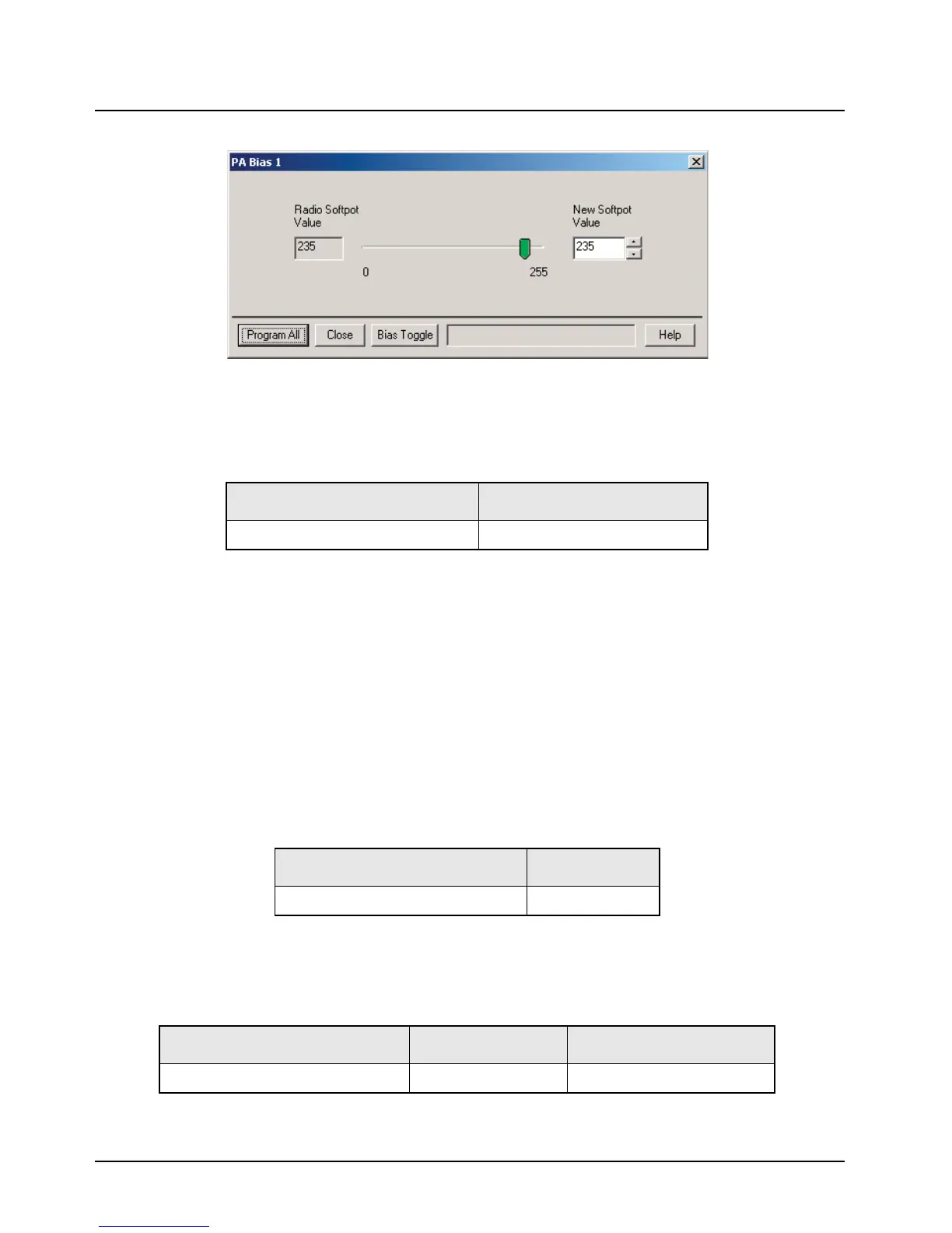
Figure 6-4. PA Bias 1 Alignment Screen
3. Read baseline current from current meter on power supply.
4. Add baseline current to device bias current to calculate target current.
5. Left-click the Bias Toggle button to apply bias to gate of device.
6. Adjust softpot value until target current is achieved within
±10%
7. Left-click the Bias Toggle button to remove bias from gate of device.
8. Left-click the Program All button to save tuned value.
9. Left-click Close button to close the screen and return to the Tuner Main Menu.
6.4.2 PA Bias 2 Alignment
NOTE: This alignment is required after replacing (or servicing) the transceiver board.
The PA Bias 2 alignment procedure adjusts the drain bias current in one of the RF power amplifier
devices:
NOTE: The antenna port should be terminated with a 50-ohm load while tuning.
1. Set the power supply voltage as indicated in Table 6-5. Set power supply current limit to 3 A.
Table 6-3. PA Bias 1 Alignment Device Bias Current
Band/Power Level Device bias current (mA)
700–800 MHz 35 W/15 W Motorcycle 250
Table 6-4. PA Bias 2 Alignment Amplifier Devices
Band/Power Level Device
700–800 MHz 35 W/15 W Motorcycle Final2
Table 6-5. Power Supply Voltage Settings
Band/Power Level Supply Voltage (V) Supply Current Limit (A)
700–800 MHz 35 W/15 W Motorcycle 13.6 15

 Loading...


