6881096C73-O June 11, 2003
Basic Theory of Operation: Frequency Generation Unit (FGU) 3-11
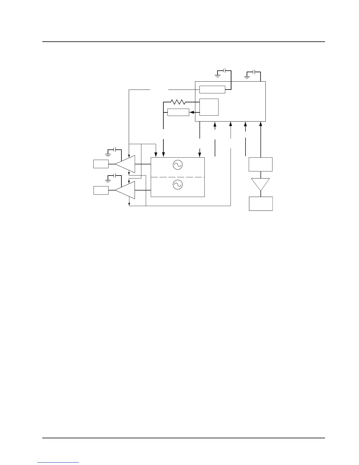
3.11 Frequency Generation Unit (FGU)
Figure 3-2. Frequency Generation Unit Diagram
The frequency generation unit (FGU) (
Figure 3-2) is comprised of a fractional-N synthesizer IC, a
16.8 MHz reference oscillator IC, two voltage-controlled oscillator (VCO) modules (receive and
transmit, containing two VCOs each), VCO buffer/amplifier circuits, and associated circuitry.
The reference oscillator IC provides a frequency standard to the fractional-N synthesizer IC, the
Abacus III digital back-end IC and to the controller section. The synthesizer turns on one of the four
VCOs (determined by mode and band of operation) and tunes it to the receiver (RX) local oscillator
(LO) or transmitter (TX) carrier frequency.
The voltage-controlled oscillator (VCO) module employs a Colpitts configuration with two bipolar
stages in a common-base, common-collector configuration. The LC tank circuit’s capacitive portion
consists of a varactor diode, coupling capacitor and a laser-trimmed capacitor for frequency
adjustment. The inductive portion consists of microstrip transmission line resonators for TX VCO and
coaxial resonators for RX VCO. Tuning is performed by the module manufacturer and is not field
adjustable. The varactor changes the oscillator frequency when the DC voltage of the steering line
changes. The output of the common base is coupled to the second transistor for impedance
buffering, and its output is coupled to respective TX/RX buffer amplifiers.
In TX mode, the transmitter VCO output is coupled to a three-stage buffer before being injected into
the power amplifier (see
“3.9 Radio-Frequency Power Amplifier (RF PA) and Output Network (ON)”
on page 3-9
). In RX mode, the receiver VCO output is buffered and amplified with a two-stage
transistor/microwave monolithic IC (MMIC) circuit. The output of the first-stage transistor is split into
two paths. One path feeds back to the synthesizer prescaler; the other path is injected into the
second-stage MMIC. The output of the MMIC provides the proper signal level for the LO port of the
RX front-end mixer (see
“3.10 700–800 Receiver Overview” on page 3-10).
The super filter supplies the voltage to the first two stages of the TX buffer and to the first-stage
transistor of the RX buffer/amplifier. The voltage for the third stage of the TX buffer is supplied by a
keyed 9.1 V source to conserve current drain while the radio is receiving. The second stage MMIC of
the RX buffer/amplifier is supplied by a 9.3 V regulator.
LoopFilter
Adapt
Buffer
Controller
RxBE
DualRxVCO
DualTxVCO
9.3V
9.1V
9.3V
3V
LVFrac-N
Synthesizer
Dual
Charge
Pump
TCXO
16.8MHz
Transmit
Modulation
AUX-
Tx/RxSelect
PreScaler
IN
SPI
SuperFilter
Steering
LineVoltage
Tx
Buffer
RxFE
Rx
Buffer
RFPA
+
-
+
-
+
-
+
-
8.2VOut
MAEPF-27588-A

 Loading...


