6881096C73-O June 11, 2003
Radio Alignment Procedures: Performance Testing 6-17
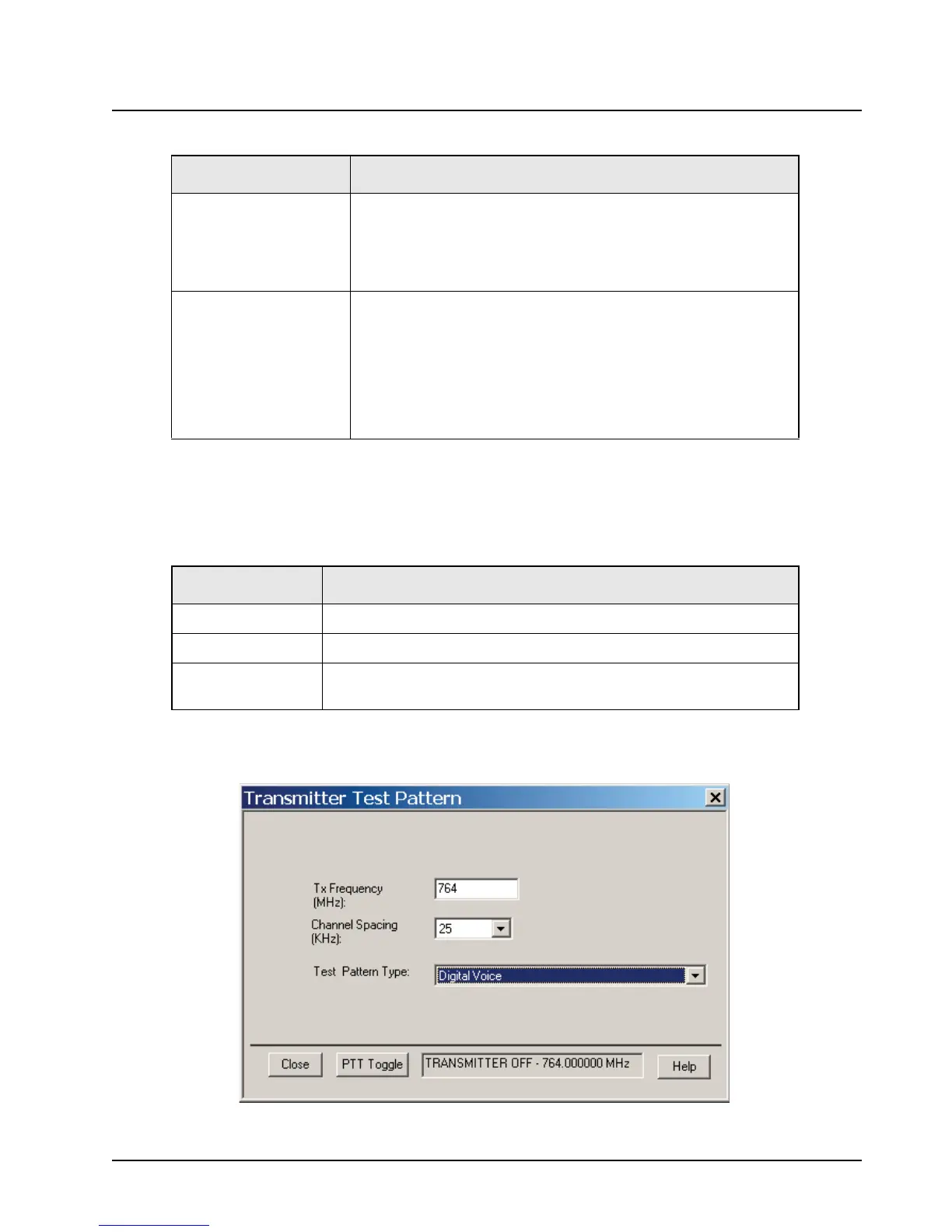
6.5.2 Transmitter Test Pattern
This procedure allows you to generate test patterns at selectable frequencies and channel spacing
to check the transmitter. The procedure contains the fields described in Table 6-17:
NOTE: Channel Spacing and Test Pattern Type fields will be grayed out while radio is transmitting.
Figure 6-14. Transmitter Test Pattern Screen
Audio Allows the user to select the audio output during a test.
Selecting External will route the same signal to the radio’s accessory
connector audio output.
Selecting Internal is not supported.
Selecting Mute will disable the audio output.
BER Integration Time Represents the amount of time during which the Bit Error Rate is to be
calculated. Remember that integration over a longer time period
results in a more precise measurement, at the expense of more time
per measurement.
NOTE: This is especially useful in fading measurements.
The range is from 0.360 to 91.8 seconds in increments of 0.360
seconds.
Table 6-17. Transmitter Test Pattern Fields
Field Description
Tx Frequency This field selects the Transmit Frequency directly in MHz.
Channel Spacing This field allows the user to select the desired transmit deviation in kHz.
Test Pattern Type This field represents the type of test pattern which will be transmitted by
the radio when the PTT Toggle button is pressed.
Table 6-16. Bit Error Rate Test Fields (Continued)
Field Description

 Loading...


