Chapter 10 Functional Block Diagrams and Connectors
This chapter contains the ASTRO XTL 5000 digital mobile radio functional block diagrams and connector locations.
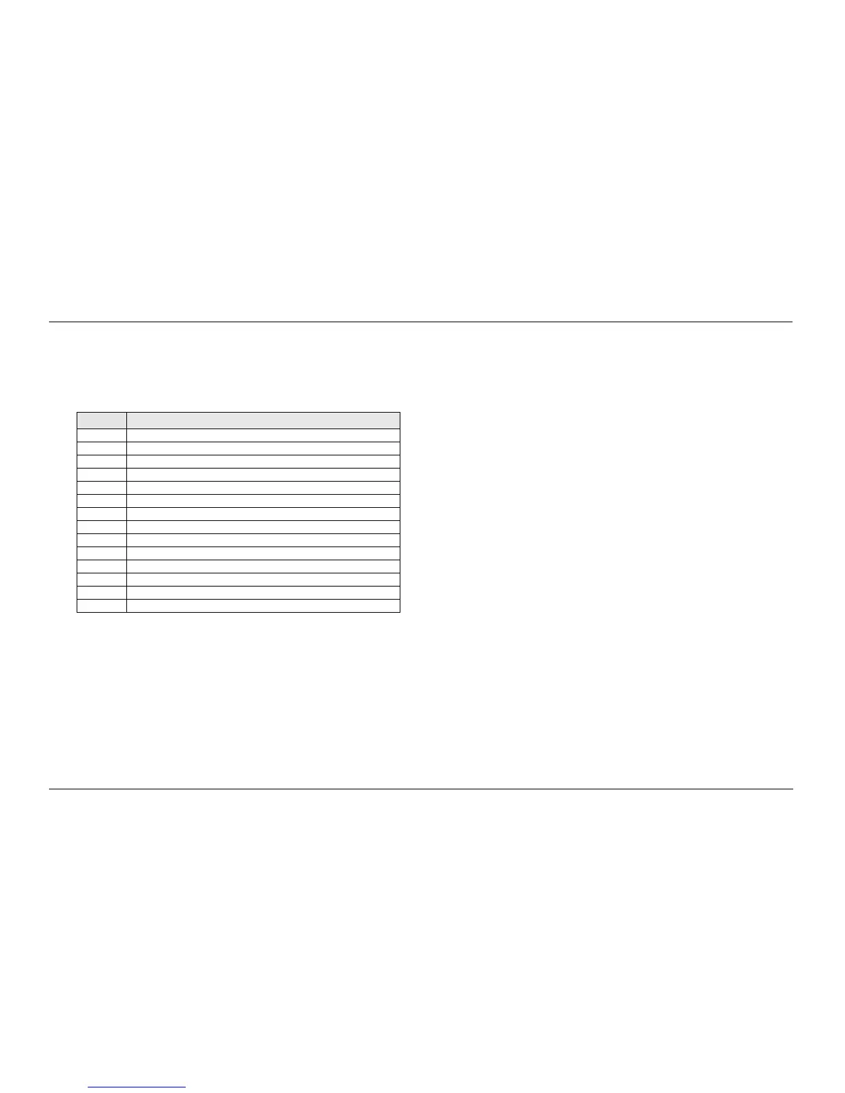
Table 10-1. Table of Functional Block Diagrams and Connectors
Page Figure Name
10-2 Figure 10-1. ASTRO XTL 5000 Functional Block Diagram
10-3 Figure 10-2. J0103 Remote-Mount Control Head Connector
10-3 Figure 10-3. J5 Control Cable for Remote-Mount Control Head
10-3 Figure 10-4. J6 Radio Operations Connector
10-3 Figure 10-5. J3 Remote-Control Cable Accessory Connector
10-3 Figure 10-6. J2 Rear Accessory Connector
10-3 Figure 10-7. P104 Microphone Jack
10-4 Figure 10-8. Dash-Mount Radio Connector Locations
10-4 Figure 10-9. Remote-Mount Radio Connector Locations
10-4 Figure 10-10. Main Board Connector Locations - Side 1
10-4 Figure 10-11. Main Board Connector Locations - Side 2
10-5 Figure 10-12. Control Head Cabling Diagram
10-6 Figure 10-13. Control Head 50-pin Connector
10-7 Figure 10-14. XTL 5000 Radio Connector Naming Scheme

 Loading...


