Functional Block Diagrams and Connectors: Connector Naming Schemes 10-7
6881096C73-O June 12, 2003
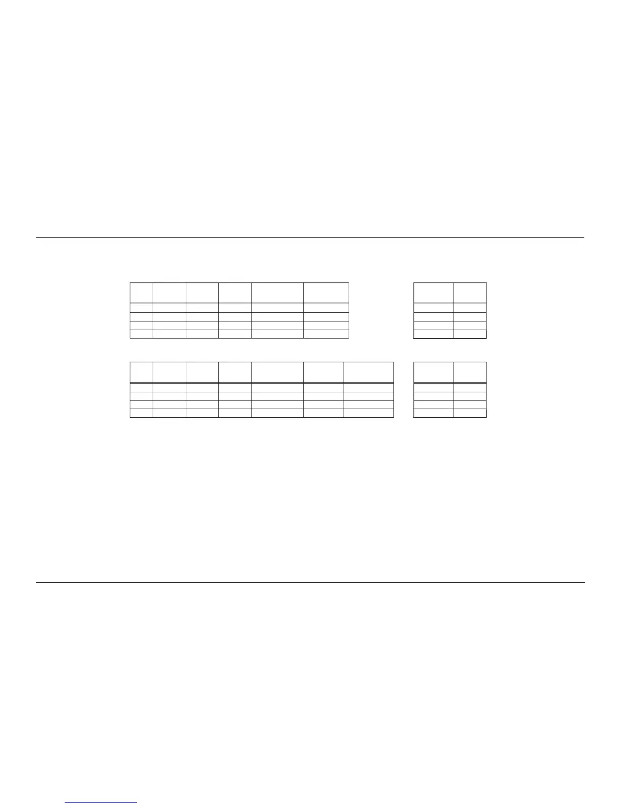
10.7 Connector Naming Schemes
Figure 10-14 illustrates the differences between the XTL 5000 radio connector computer data and control signal names as these signals pass from one connector to another.
Figure 10-14. XTL 5000 Radio Connector Naming Scheme
J6 pin number
J6 pin name
"pin alternate
name"
EIA compatible name at
remote connector = J6
EIA pin number
and name at J6
TX_
DCE
RX_DCE
RTS_DCE
CTS_DCE
becomes TX
becomes RX
becomes RTS
becomes CTS
TX_
DCE = pin 2
RX_
DCE = pin 3
RTS_
DCE = pin 8
CTS_
DCE = pin 7
pin 2 = TX_
DCE
pin 3 = RX_DCE
pin 17 = RTS_DCE
pin 4 = CTS_DCE
HKN6122 data
cable DB9 (Female)
= "DCE" interface
RS232_RXD
RS232_TDX
RS232_CTS
RS232_RTS
J6-3
J6-17
J6-2
J6-4
Radio pin
direction
REMOTE MOUNT INTERCONNECT BOARD CONNECTOR naming schemes Connecting to a computer = DTE device:
output
input
output
input
pin 2 = RX_DTE
pin 3 = TX_DTE
pin 8 = CTS_DTE
pin 7 = RTS_DTE
NOTE: TX to RX and RTS to CTS
DB9 (Male) serial
port connector
= "DTE" interface
Data device
pin direction
input
output
input
output
MAEPF-27610-A
--
< >
--
< >
--
< >
--
< >
J2 pin number
J2 pin name
"pin alternate
name"
EIA compatible name at
REAR connector = J2
TX_
DCE
RX_DCE
RTS_DCE
CTS_DCE
no change
no change
becomes RTS
becomes CTS
TX_
DCE = pin 2
RX_
DCE = pin 3
RTS_
DCE = pin 8
CTS_
DCE = pin 7
P2 rear accessory
cable DB9 (Female)
= "DCE" interface
UARTA_TX
UARTA_RX
UARTA_
CTS
UARTA_RTS
J2-5
J2-10
J2-4
J2-11
Radio pin
direction
REAR CONNECTOR naming schemes Connecting to a computer = DTE device:
output
input
output
input
pin 2 = RX_DTE
pin 3 = TX_DTE
pin 8 = CTS_DTE
pin 7 = RTS_DTE
NOTE: TX to RX and RTS to CTS
DB9 (Male) serial
port connector
= "DTE" interface
Data device
pin direction
input
output
input
output
--
< >
--
< >
--
< >
--
< >

 Loading...


