LCD Controller
18-4
MPC823e REFERENCE MANUAL
MOTOROLA
LCD CONTROLLER
18
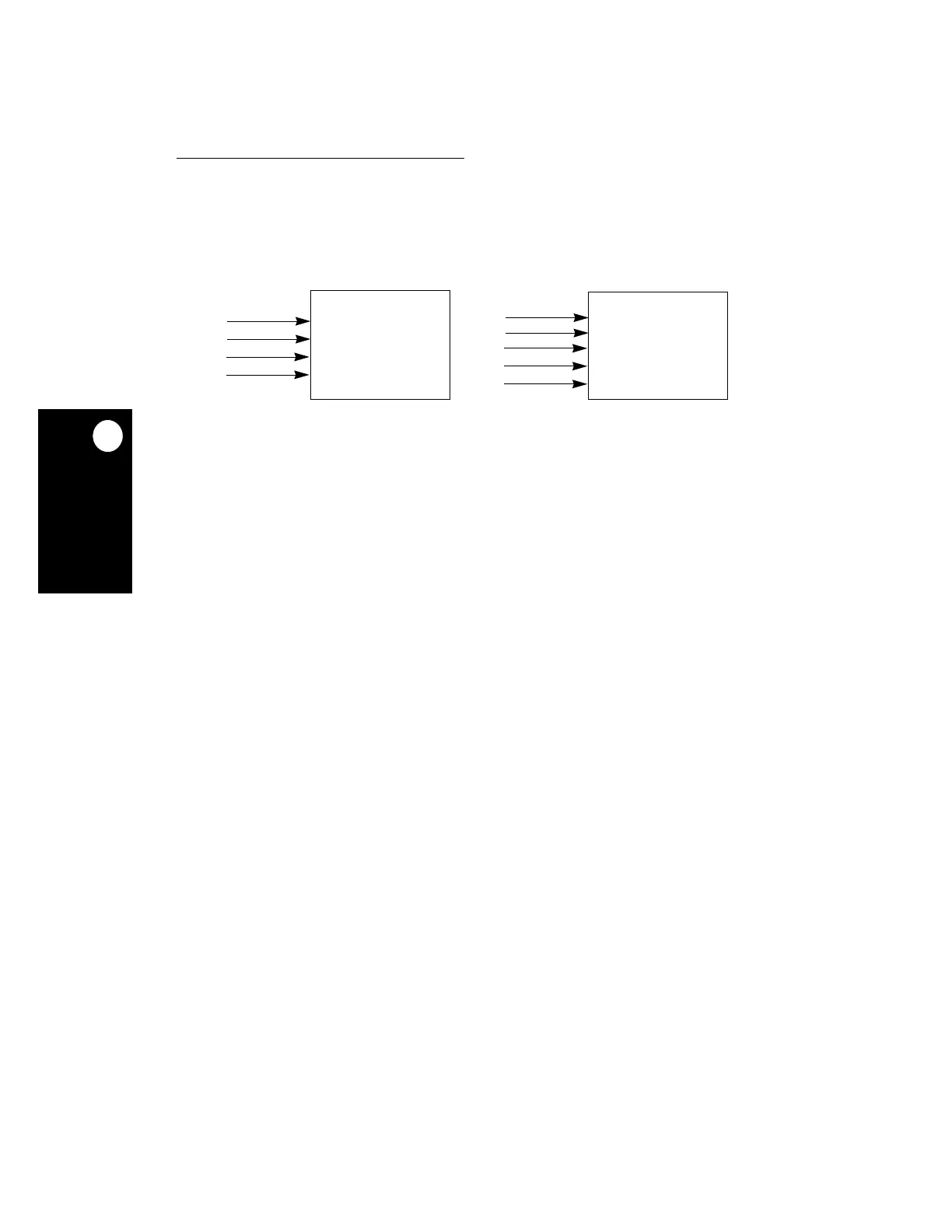
18.1.2.1 PASSIVE LCD INTERFACE.
A passive LCD panel interface uses X and Y shift
registers to operate. The X shift register is used to display a column and the Y shift register
is used to display a row. The LCD controller fills the shift register, provides framing, and
reverses the display polarity from frame-to-frame or line-to-line.
A passive LCD interface consists of several parallel data bits that are shifted into the X shift
register by the shift clock. After the shift register is full, a latch signal transfers the pixels from
the shift register to driver latches and moves the Y pointer down one line. At this point, the
shift operation continues to the next line and after all the lines are scanned, the frame signal
moves the Y pointer to the beginning of the frame. The LCD controller also accesses the
frame buffer. The panel can be single- or dual-scan and the dual-scan function is
accomplished by splitting the Y dimension. For single-scan panels, the LCD controller only
has one buffer. For dual-scan panels, the LCD controller must have one upper and one
lower frame buffer. In most LCD panels, you need control to kill any DC biases that build up
during normal operation. A signal that inverts the polarity of the voltages is presented to the
LCD panel. Usually, this signal toggles every few frames (1–20).
Figure 18-3. Passive Interfaces
SHIFT
LOAD
FRAME
D[0:x]
PASSIVE SINGLE-SCAN
SHIFT
LOAD
FRAME
UD[0:x]
LD[0:x]
PASSIVE DUAL-SCAN
x = [0, 3, 7] x= [1, 3]
PANEL
PANEL
 Loading...

