LCD Controller
18-6
MPC823e REFERENCE MANUAL
MOTOROLA
LCD CONTROLLER
18
18.2 THE MPC823e LCD CONTROLLER
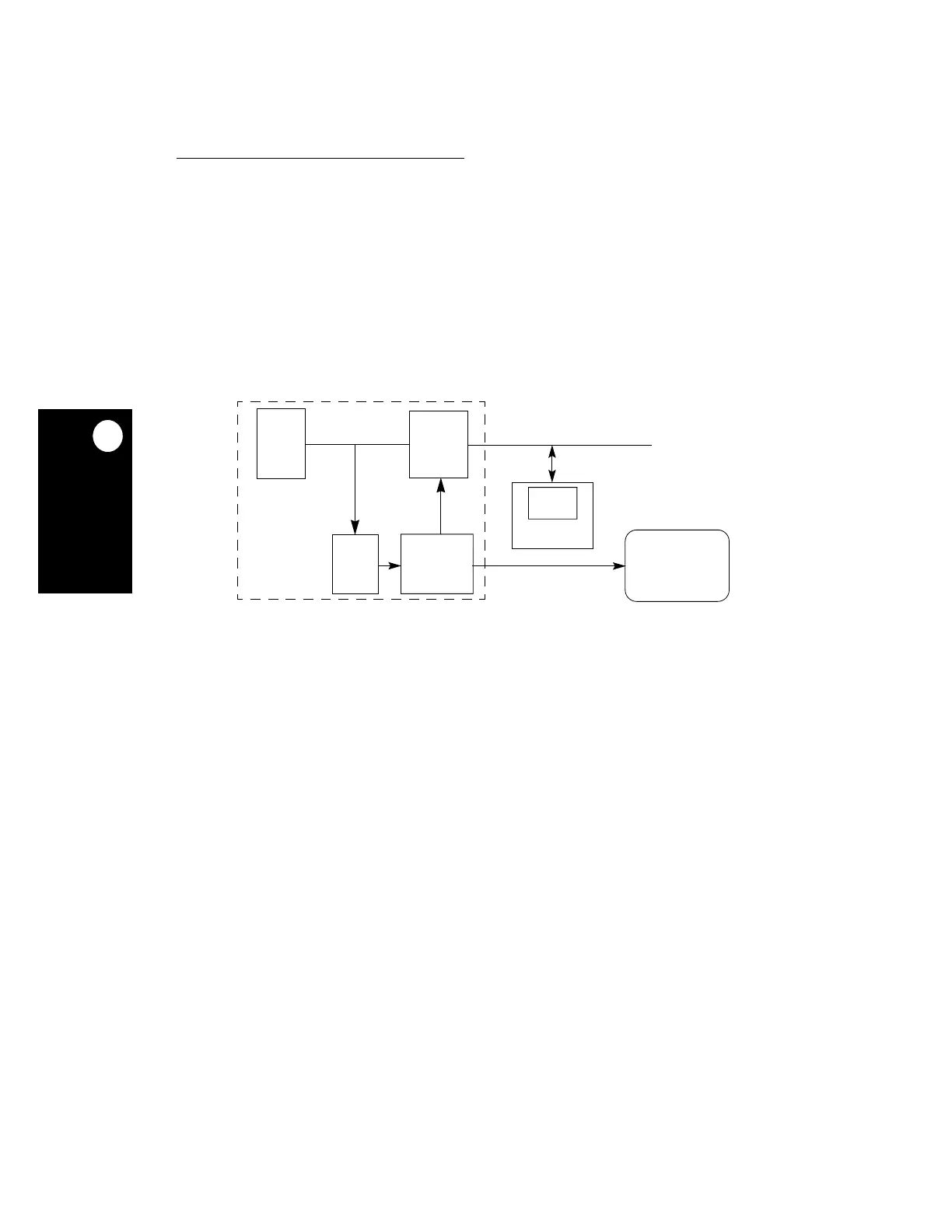
The MPC823e LCD controller is initialized by the core, which provides the frame buffer
address, operational modes, and various configuration bits that the LCD controller needs to
operate. After it is enabled, the LCD controller requests the DMA to fetch the frame buffer
data. The frame buffer is always organized in rows and columns. Depending on the interface
you are using, the data is then interpreted for grayness or color and frame format. The data
is then packed according to the model you have chosen. If you are using a split panel
display, you must initialize two buffers—one for each panel display. The LCD controller uses
continuous DMA to feed the display. Figure 18-5 illustrates a typical MPC823e LCD system.
MPC823e
Figure 18-5. The MPC823e LCD System
LCD
CONTROLLER
LCD
FRAME
BUFFER
PANEL
DMA
SYSTEM
SYSTEM BUS
CORE
INTERNAL BUS
INTERFACE
UNIT
IRQ
SYSTEM RAM