LCD Controller
MOTOROLA MPC823e REFERENCE MANUAL 18-21
LCD CONTROLLER
18
18.4 REGISTER MODEL
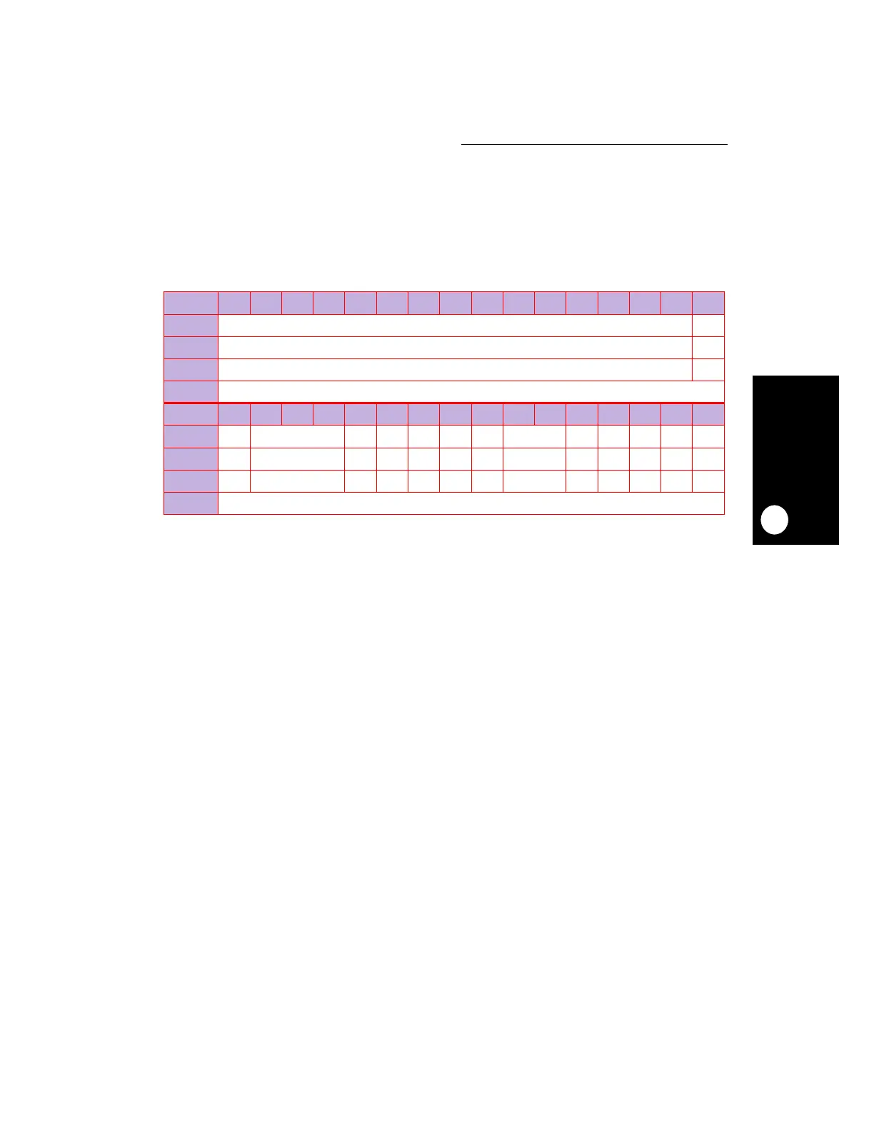
18.4.1 LCD Controller Configuration Register
The 32-bit, memory mapped, read/write LCD controller configuration register (LCCR) holds
the mode and configuration parameters that you can use to operate your LCD panel.
BNUM—Number of Bursts
This field contains the number of burst cycles required for one refresh cycle.
EIEN—Exception Interrupt Enable
0 = The underrun or bus error interrupt is disabled.
1 = The underrun or bus error interrupt is enabled.
IEN—Interrupt Enable
0 = The end-of-frame interrupt is disabled.
1 = The end-of-frame interrupt is enabled.
IRQL—Interrupt Request Level
This field contains the priority request level of the LCD controller’s interrupt that is sent to
the system interface unit. Refer to Section 12.3.3 Programming the Interrupt Controller
for more information. This will generate an interrupt request level with a vector in the SIVEC
register if enabled with the SIMASK register. Both EOF and the exception interrupts use the
same request level.
CLKP—Clock Polarity
0 = The SHIFT/CLK pin polarity is active high.
1 = The SHIFT/CLK pin polarity is active low.
LCCR
BIT 0 1 2 3 4 5 6 7 8 9 10 11 12 13 14 15
FIELD
BNUM EIEN
RESET
00
R/W
R/W R/W
ADDR
(IMMR & 0xFFFF0000) + 0x840
BIT 16 17 18 19 20 21 22 23 24 25 26 27 28 29 30 31
FIELD
IEN IRQL CLKP OEP HSP VSP DP BPIX LBW SPLT CLOR TFT PON
RESET
0 0 00000 0 00000
R/W
R/W R/W R/W R/W R/W R/W R/W R/W R/W R/W R/W R/W R/W
ADDR
(IMMR & 0xFFFF0000) + 0x842
 Loading...

