Video Controller
19-10
MPC823e REFERENCE MANUAL
MOTOROLA
VIDEO CONTROLLER
19
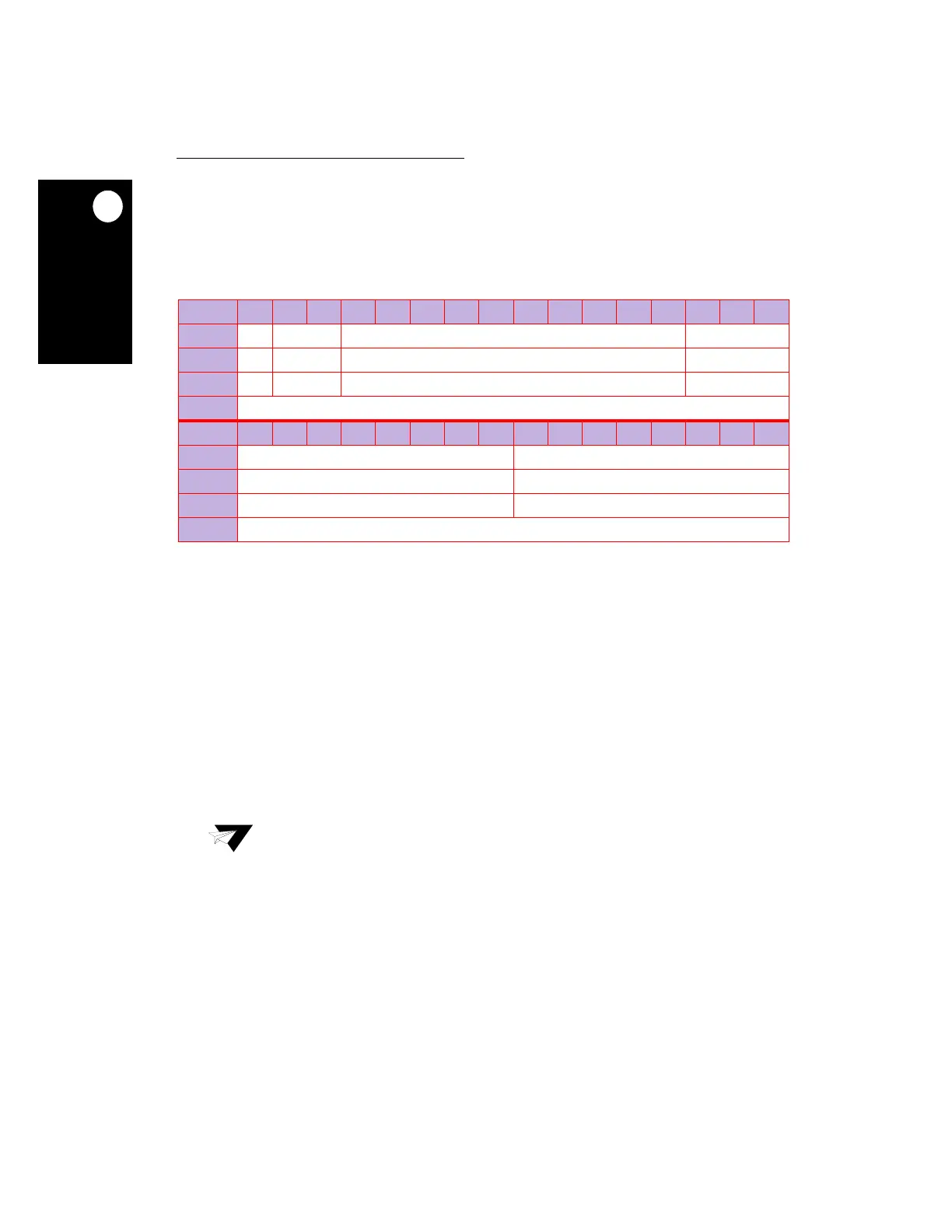
19.3.5 Video Frame Configuration Register (Set 0)
The 32-bit, memory mapped, read/write video frame configuration register set 0 (VFCR0)
holds the display horizontal and vertical size, as well as the gap between two sequential
lines.
SFB0—Single Frame Buffer 0
This bit controls whether the video controller displays an image from a single frame buffer
(A) or from both frame buffers (A and B).
0 = Frame B is valid.
1 = Frame B is not valid.
Bits 1–2—Reserved
These bits are reserved and must be set to 0.
VPC0—Vertical Pixel Count 0
This field defines the number of lines for a field.
GAP0—Gap 0
This field defines the gap in memory between the end of a line and the beginning of the next
line in full burst units. For regular noninterlace mode, this field is set to 0. For regular
interlace mode, it is set to the value in the NBPL0 field. For example, hardware pan/scroll
options in a zoomed buffer can be implemented by using the GAP0 field with an appropriate
field buffer start address. For example, with 720 pixels in YC
r
C
b
format, GAP0 must be 0x5A.
VFCR0
BIT
0 1 2 3 4 5 6 7 8 9 10 11 12 13 14 15
FIELD
SFB0 RESERVED VPC0 GAP0
RESET
00 0 0
R/W
R/W R/W R/W R/W
ADDR
(IMMR & 0xFFFF0000) + 0x810
BIT
16 17 18 19 20 21 22 23 24 25 26 27 28 29 30 31
FIELD
GAP0 NBPL0
RESET
00
R/W
R/W R/W
ADDR
(IMMR & 0xFFFF0000) + 0x812
Note:
The value of the VPC0 field must be non-zero or an error will occur.
 Loading...

