Development Capabilities and Interface
MOTOROLA
MPC823e REFERENCE MANUAL
20-7
DEVELOPMENT
20
CAPABILITIES & INTERFACE
20.2.1.2.4 Detecting the Trace Window Start Address.
When using back trace, latching
VF, VFLS, and the address of the program trace cycles must start immediately after reset is
negated. The start address is the first address in the program trace cycle buffer. When using
window trace, latching of VF, VFLS, and the address of the program trace cycles must start
immediately after the first VSYNC is recognized on the VF pins. The start address of the
trace window must be calculated according to the first two VF pin reports. Assume VF1 and
VF2 are the first two VF pin reports and T1 and T2 are the two addresses of the first two
cycles marked with the program trace cycle attribute that were latched in the trace buffer.
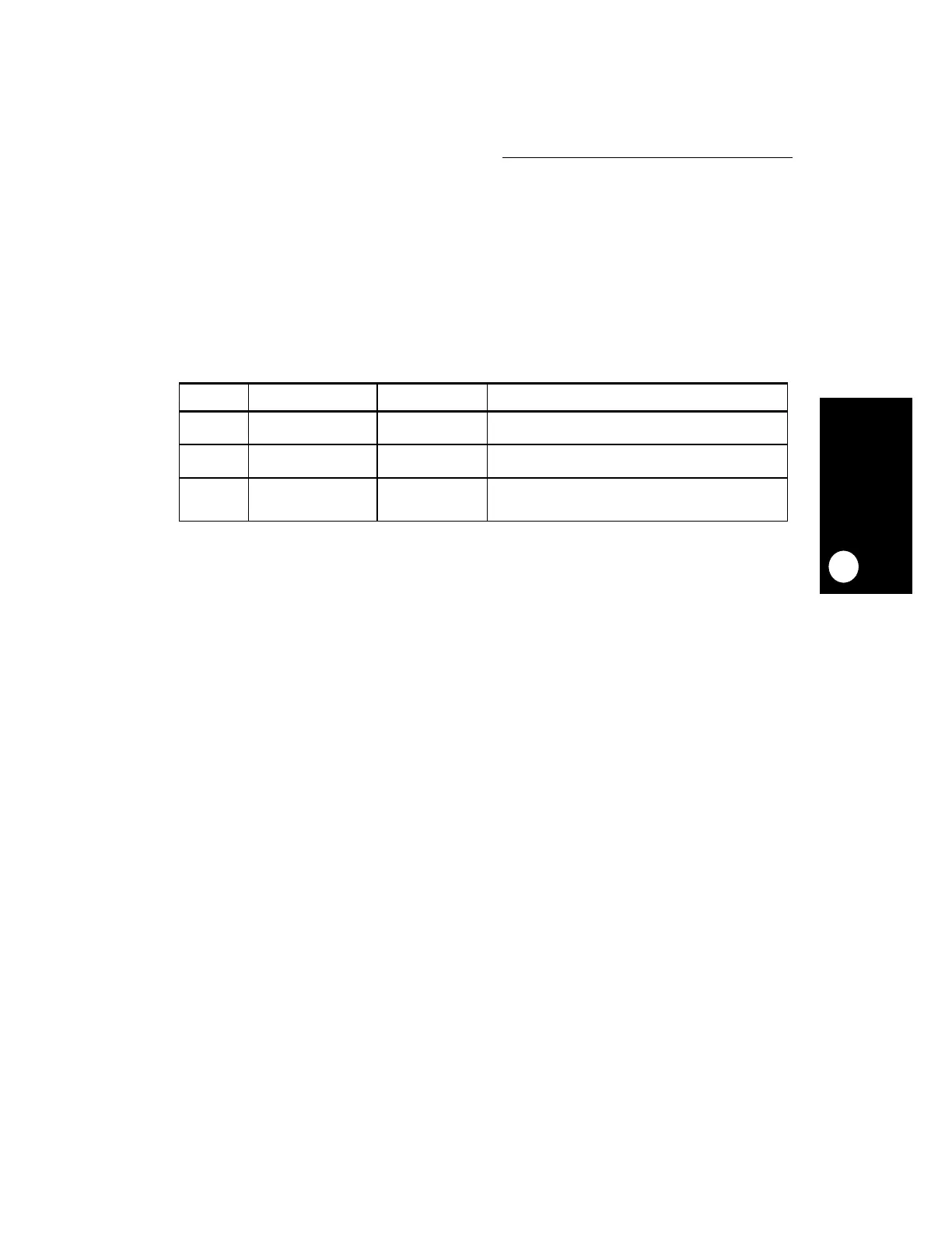
Use the following table to calculate the trace window start address.
20.2.1.2.5 Detecting VSYNC Assertion/Negation.
Because the VF pins are used to
report both instruction type and queue flush information, the external hardware must be
cautious when trying to detect the assertion/negation of VSYNC. When VF equals 011, it is
a VSYNC assertion/negation report only if the prior value of VF was 000, 001, or 010.
20.2.1.2.6 Detecting the Trace Window End Address.
The information on the status
pins that describes the last fetched instruction and last queue/history buffer flush changes
every clock. Program trace cycles are only generated on the external bus when the system
interface unit arbitrates over the external bus. Therefore, there is a delay between the report
that a program trace cycle is performed and the actual time that this cycle can be detected
on the external bus.
When you negate VSYNC using the serial interface of the development port, the core delays
reporting that VSYNC occurred on the VF pins until all addresses marked with the program
trace cycle attribute are externally visible. Therefore, the external hardware must stop
sampling VF, VFLS, and the address of the program trace cycles immediately after VF
equals VSYNC. The last two instructions reported on the VF pins are not always valid.
Therefore, at the last stage of the reconstruction software, ignore the last two instructions.
Table 20-2. Detecting the Trace Buffer Starting Point
VF1 VF2 STARTING POINT DESCRIPTION
011
VSYNC
001
Sequential
T1 VSYNC is asserted and followed by a sequential
instruction. the start address is T1.
011
VSYNC
110
Branch Direct Taken
T1 - 4 +
Offset(T1 - 4)
VSYNC is asserted and followed by a taken direct branch.
the start address is the target of the direct branch.
011
VSYNC
101
Branch Indirect Taken
T2 VSYNC is asserted and followed by a taken indirect
branch. the start address is the target of the indirect
branch.