Development Capabilities and Interface
20-8
MPC823e REFERENCE MANUAL
MOTOROLA
DEVELOPMENT
20
CAPABILITIES & INTERFACE
20.2.1.3 COMPRESSION OF CANCELLED INSTRUCTIONS.
To store all the information
generated on the pins during program trace (5 bits per clock + 30 bits per show cycle), a
large memory buffer is required. However, since this information includes events that were
canceled, compression is possible and can be very beneficial in this situation. External
hardware can be added to eliminate all canceled instructions and reports only on taken or
not taken branches, indirect flow change, and the number of sequential instructions after the
last flow change.
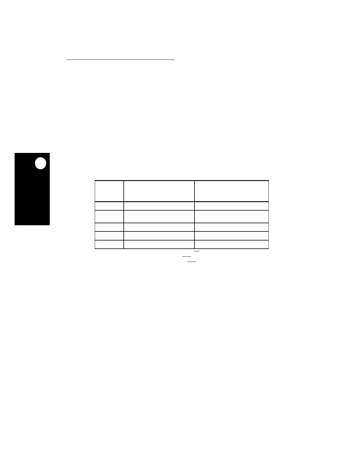
20.2.2 Controlling Instruction Fetch Show Cycles
Instruction fetch show cycles are controlled by the bits in the ICTRL register and the state
of the VSYNC signal. The following table defines the level of fetch show cycles generated
by the core and the types of fetch show cycles determined by the ISCT_SER field. A cycle
marked with the program trace cycle attribute is generated for any change in the state of
VSYNC.
20.3 GENERATING WATCHPOINTS AND BREAKPOINTS
When detected, watchpoints are reported to the external world on dedicated pins, but do not
change the timing and flow of the machine. When breakpoints are detected, they force the
machine to branch to the appropriate exception handler. The core supports watchpoints that
are generated inside the core as well as breakpoints that are generated inside and outside
the core.
In the core, as in other RISC processors, saving and restoring the machine state on the
stack during exception handling is accomplished in the software. When the software is in the
middle of saving and restoring, the MSR
RI
bit is cleared. Exceptions are handled by the core
when the MSR
RI
bit is clear and they result in a nonrestartable machine state. For more
information refer to
Section 6.3.4.1 Restartability After An Interrupt
.
Table 20-3. Fetch Show Cycle Types
VSYNC
ISCT_SER INSTRUCTION
FETCH SHOW CYCLE
CONTROL FIELD
SHOW CYCLES
GENERATED
X 000 All Fetch Cycles
X X01 All Change of Flow (Direct and
Indirect)
X X10 All Indirect Change of Flow
0 X11 No Show Cycles Are Performed
1 X11 All Indirect Change of Flow
NOTE: Only cycles that access storage assert the TS
signal. All cycles that involve “show
cycles” are marked by asserting the STS
signal. When you need to sample the
show cycle address and attributes, the STS
signal must be enabled by
programming the DBGC field of the SIUMCR. See
Section 12.12.1.1 SIU Module
Configuration Register
for details.