Development Capabilities and Interface
20-50 MPC823e REFERENCE MANUAL MOTOROLA
DEVELOPMENT
20
CAPABILITIES & INTERFACE
CHBMSK—Byte Mask for Comparator H
0000 = All bytes are not masked.
0001 = Last byte of the word is masked.
•
•
•
1111 = All bytes are masked.
Bits 30–31—Reserved
These bits are reserved and must be set to 0.
20.6.2.7 LOAD/STORE SUPPORT AND-OR CONTROL REGISTER. The load/store
support AND-OR control (LCTRL2) register is used to control the bit masks for load/store
data comparisons. Watchpoint programming consists of three control register fields—
LWxIA, LWxLA, and LWxLD. All three conditions must be detected to assert a watchpoint.
The reset value of this register is 0x00000000.
LW0EN—First Load/Store Watchpoint Enable
0 = Watchpoint not enabled (reset value).
1 = Watchpoint enabled.
LW0IA—First Load/Store Watchpoint I-Address Watchpoint Selection
00 = First instruction watchpoint.
01 = Second instruction watchpoint.
10 = Third instruction watchpoint.
11 = Fourth instruction watchpoint.
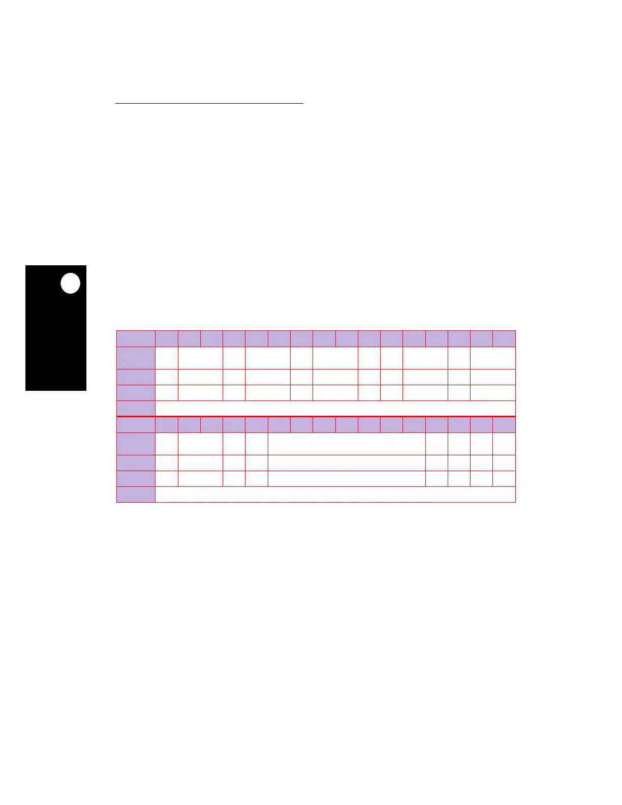
LCTRL2
BIT 0 1 2 3 4 5 6 7 8 9 10 11 12 13 14 15
FIELD
LW0E
N
LW0IA
LW0IA
DC
LW0LA
LW0L
ADC
LW0LD
LW0L
DDC
LW1E
N
LW1IA
LW1IA
DC
LW1LA
RESET
00000000000
R/W
R/W R/W R/W R/W R/W R/W R/W R/W R/W R/W R/W
SPR
157
BIT 16 17 18 19 20 21 22 23 24 25 26 27 28 29 30 31
FIELD
LW1L
ADC
LW1LD
LW1L
DDC
BRKN
OMSK
RESERVED
DLW0
EN
DLW1
EN
SLW0
EN
SLW1
EN
RESET
0000 0 0000
R/W
R/W R/W R/W R/W R/W R/W R/W R/W R/W
SPR
157