IEEE 1149.1 Test Access Port
21-2
MPC823e REFERENCE MANUAL
MOTOROLA
IEEE 1149.1 TEST
21
ACCESS PORT
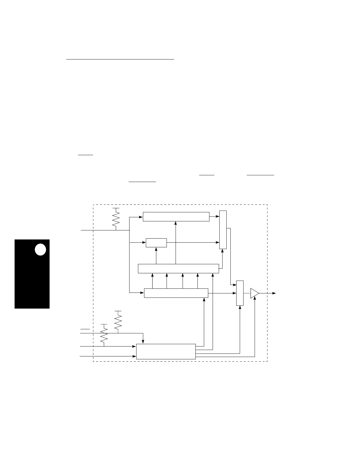
The MPC823e implementation includes a TAP controller, a 4-bit instruction register, and two
test registers (a 1-bit bypass register and a 397-bit boundary scan register). An overview of
the MPC823e scan chain implementation is illustrated in the figure below. The TAP
controller consists of the following signals:
• TCK—A test clock input to synchronize the test logic.
• TMS—A test mode select input (with an internal pull-up resistor) that is sampled on the
rising edge of TCK to sequence the TAP controller’s state machine.
• TDI—A test data input (with an internal pull-up resistor) that is sampled on the rising
edge of TCK.
• TDO—A three-stateable test data output that is actively driven in the shift-IR and
shift-DR controller states. TDO changes on the falling edge of TCK.
• TRST
—An asynchronous reset with an internal pull-up resistor that provides TAP
controller initialization and other logic required by the standard. For normal operation of
the MPC823e, this signal pin must make a level transition to low before initialization
begins. Typically, if the TAP is used, connect the TRST
signal to the PORESET through
a diode (cathode to PORESET
).
Figure 21-1. Test Logic Block Diagram
BOUNDARY SCAN REGISTER
BYPASS
M
U
X
INSTRUCTION APPLY & DECODE REGISTER
4-BIT INSTRUCTION REGISTER
M
U
X
TDO
TDI
TMS
TCK
TRST
012
TAP CONTROLLER
3
 Loading...

