Memory Controller
MOTOROLA MPC823e REFERENCE MANUAL 15-15
MEMORY CONTROLLER
15
EHTR—Extended Hold Time on Read
When this bit is set, it adds one clock cycle after a read from the current bank and any CPU
write or read to a different bank.
0 = Timing is defined by the memory controller.
1 = Extended hold time is defined on the current read access.
Bit 31—Reserved
This bit is reserved and must be set to 0.
15.3.1.3 MEMORY STATUS REGISTER. The memory status (MSTAT) register reports
parity and write-protect errors encountered during an external bus access initiated by the
memory controller. To clear a specific bit, write a one to it (writing zero has no effect).
PER0—Parity Error Bank 0
When this bit is set it indicates that a parity error was detected during a Bank 0 read cycle
initiated by the memory controller.
PER1—Parity Error Bank 1
When this bit is set it indicates that a parity error was detected during a Bank 1 read cycle
initiated by the memory controller.
PER2—Parity Error Bank 2
When this bit is set it indicates that a parity error was detected during a Bank 2 read cycle
initiated by the memory controller.
PER3—Parity Error Bank 3
When this bit is set it indicates that a parity error was detected during a Bank 3 read cycle
initiated by the memory controller.
PER4—Parity Error Bank 4
When this bit is set it indicates that a parity error was detected during a Bank 4 read cycle
initiated by the memory controller.
PER5—Parity Error Bank 5
When this bit is set it indicates that a parity error was detected during a Bank 5 read cycle
initiated by the memory controller.
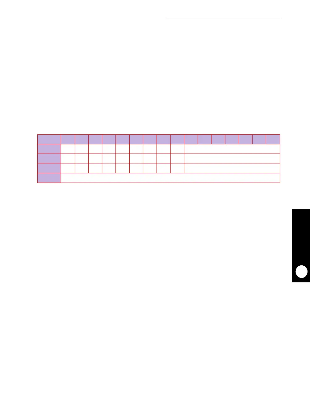
MSTAT
BIT 0 1 2 3 4 5 6 7 8 9 10 11 12 13 14 15
FIELD
PER0 PER1 PER2 PER3 PER4 PER5 PER6 PER7 WPER RESERVED
RESET
000000000 0
R/W
R/W R/W R/W R/W R/W R/W R/W R/W R/W R/W
ADDR
(IMMR & 0xFFFF0000) + 0x178