Memory Controller
MOTOROLA MPC823e REFERENCE MANUAL 15-27
MEMORY CONTROLLER
15
15.3.1.9 MEMORY PERIODIC TIMER PRESCALER REGISTER. The memory periodic
timer prescaler register (MPTPR) defines the divisor of the BRGCLK used as the memory
periodic timer input clock. Refer to Section 5.3.4 Internal Clock Signals for details.
PTP—Periodic Timers Prescaler
This field determines the division factor that is shown below.
001x xxxx = Divide by 2.
0001 xxxx = Divide by 4.
0000 1xxx = Divide by 8.
0000 01xx = Divide by 16.
0000 001x = Divide by 32.
0000 0001 = Divide by 64.
1xxx xxxx = Reserved.
01xx xxxx = Reserved.
Bits 8–15—Reserved
These bits are reserved and must be set to 0.
15.4 THE GENERAL-PURPOSE CHIP-SELECT MACHINE
The general-purpose chip-select machine (GPCM) allows a glueless and flexible interface
between the MPC823e, SRAM, EPROM, FEPROM, ROM devices, and external
peripherals. The GPCM contains three basic register groups that you can use to configure
it—base registers 0–7, option registers 0–7, and the memory status register.
15.4.1 Configuration
If the MS field in the BRx of the selected bank selects the general-purpose chip-select
machine, the attributes for the memory cycle initiated are taken from the ORx. These
attributes include the CSNT, ACS, SCY, TRLX, EHTR, and SETA fields. See Table 15-2 for
signal behavior and system response.
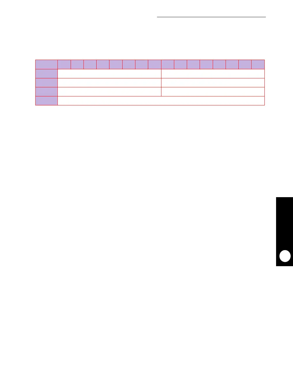
MPTPR
BIT 0 1 2 3 4 5 6 7 8 9 10 11 12 13 14 15
FIELD PTP RESERVED
RESET 00000001 00000000
R/W R/W R/W
ADDR (IMMR & 0xFFFF0000) + 0x17A