Memory Controller
15-40
MPC823e REFERENCE MANUAL
MOTOROLA
MEMORY CONTROLLER
15
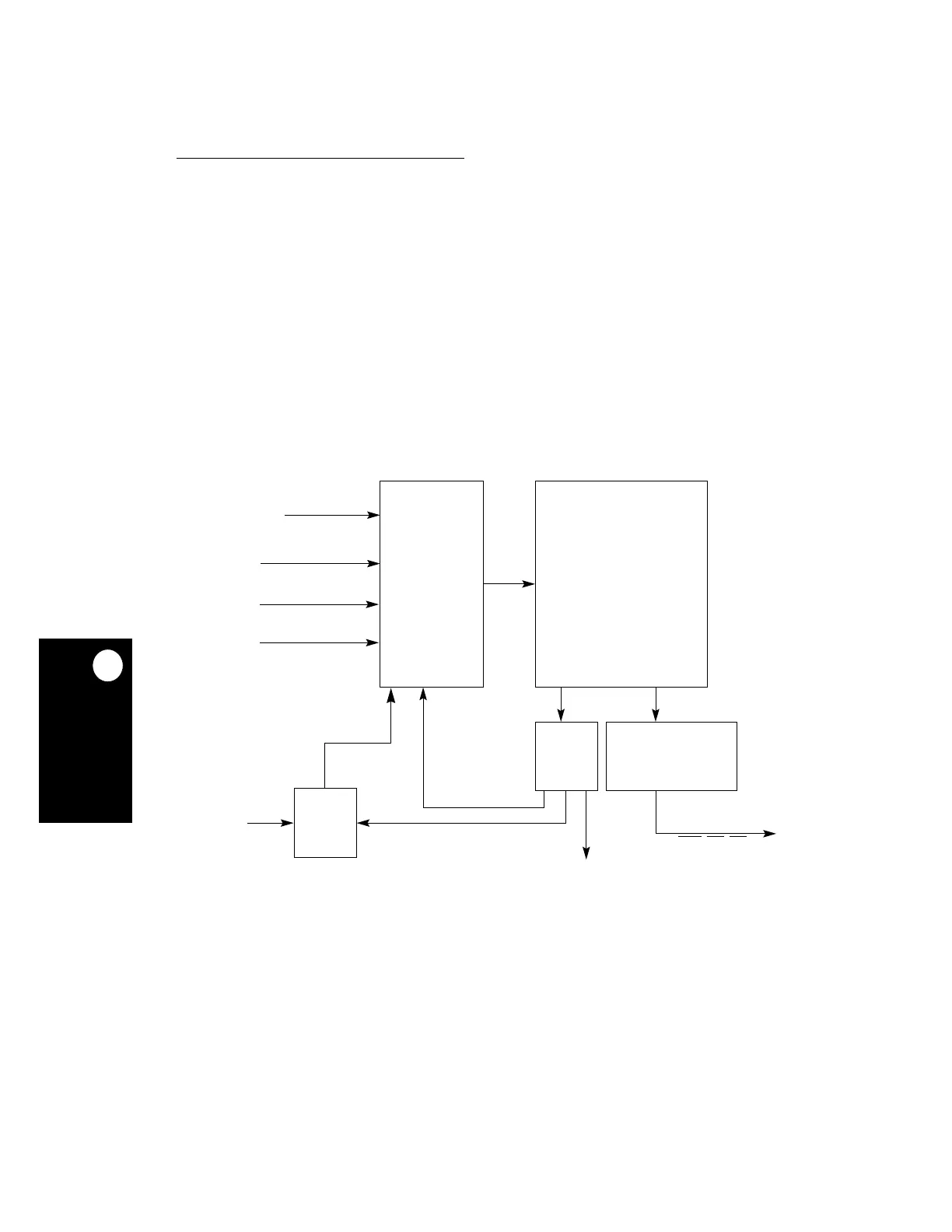
15.5 USER-PROGRAMMABLE MACHINES
Each of the two user-programmable machines (UPMs) is a flexible interface that connects
to a wide range of memory devices. At the heart of each UPM is an internal memory RAM
array that specifies the logical value driven on the external memory controller pins for a
given clock cycle. Each word in the RAM array provides bits that allow a memory access to
be controlled with a resolution of one quarter of the system clock period on the byte-select
and chip-select lines. Figure 15-20 illustrates the basic operation of each UPM. A UPM cycle
is initiated when:
• Any internal or external master requests an external memory access
• A memory periodic timer expires and requests a transaction
• A transfer error or reset generates an exception request
• The memory command register receives a
RUN
command (software) from the CPU
The RAM array contains 32-bit entries referred to as RAM words. If the UPM reads a RAM
word with the WAEN bit set, the external UPWAITx signal is sampled and synchronized by
the memory controller and the current request is frozen. The signal timing generator will load
the RAM word from the RAM array to drive the general-purpose lines, byte-selects, and
chip-selects.
Figure 15-20. User-Programmable Machine Block Diagram
SIGNALS
TIMING GENERATOR
INTERNAL
SIGNALS
LATCH
ARRAY
GENERATOR
INTERNAL/EXTERNAL MEMORY
MEMORY PERIODIC TIMER
SOFTWARE REQUEST
RAM
ARRAY
INCREMENT
REQUEST
ACCESS REQUEST
(LAST = 0)
WAIT
REQUEST
LOGIC
WAEN BIT
HOLD
INDEX
UPWAIT
INDEX
GPL
x, BSx, CSx
INTERNAL CONTROLS
INDEX
EXCEPTION REQUEST