Memory Controller
MOTOROLA
MPC823e REFERENCE MANUAL
15-57
MEMORY CONTROLLER
15
MEMORY CONTROLLER
15
The uppermost byte select (BS0
) signal indicates that the most-significant eight bits of the
data bus (D0-7) contain valid data during a cycle and the upper-middle byte-select (BS1
)
indicates that the upper-middle eight bits of the data bus (D[8-15]) signal contain valid data
during a cycle. The lower-middle byte-select (BS2
) indicates that the lower-middle eight bits
of the data bus (D[16-23]) contain valid data during a cycle and the lowest byte-select (BS3
)
indicates that the least-significant eight bits of the data bus (D[24-31]) contain valid data
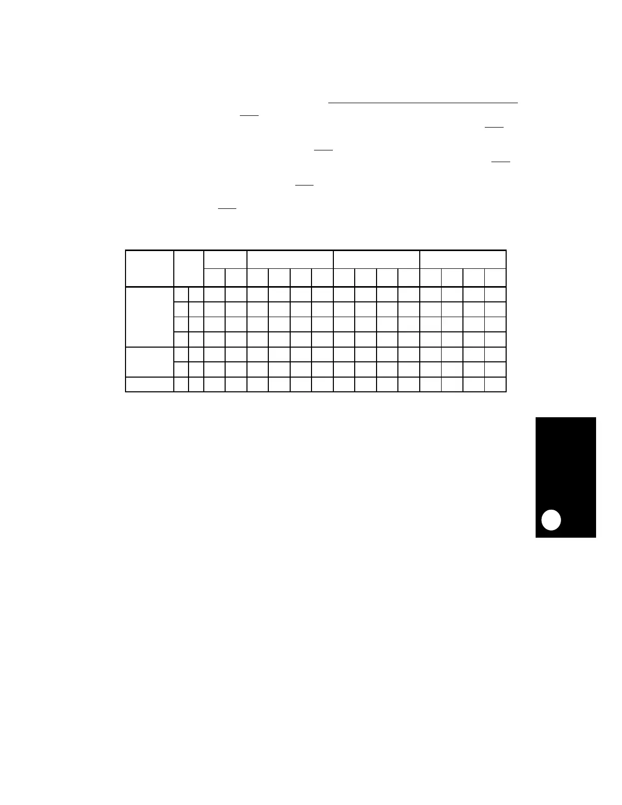
during a cycle. The manner in which the BSx
signals affect 32-, 16-, and 8-bit accesses is
shown in Table 15-5. It must be noted that for a periodic timer request and a memory
command request, the BSx
signals are only determined by the port size of the bank.
Table 15-5. Enabling Byte-Selects
TRANSFER
SIZE
TSIZx ADDRESS 32-BIT PORT SIZE 16-BIT PORT SIZE 8-BIT PORT SIZE
A30 A31 BS0 BS1 BS2 BS3 BS0 BS1 BS2 BS3 BS0 BS1 BS2 BS3
Byte 0 1 0 0 X X X
01 0 1 X X X
01 1 0 X X X
01 1 1 X X X
Half-Word 1 0 0 0 X X X X X
1010 XXXX X
Word 0 0 0 0 XXXXXX X