Communication Processor Module
16-34 MPC823e REFERENCE MANUAL MOTOROLA
DSP
COMMUNICATION
16
PROCESSOR MODULE
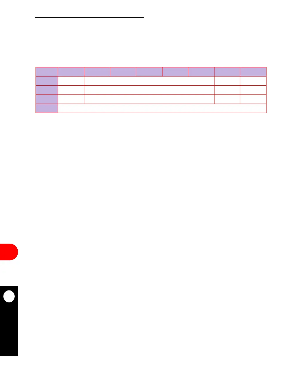
16.3.3.4 DSP MASK REGISTER. The 8-bit read/write SDMA mask register (SDMR) is
used to mask the DSP interrupts and has the same bit format as the SDSR. If a bit in the
SDMR is a 1, the corresponding interrupt in the SDSR is enabled and if it is zero, the
corresponding interrupt is masked. This register is cleared by reset.
SBER—SDMA Channel Bus Error (SDMA function)
0 = Disable the interrupt.
1 = Enable the interrupt.
Bits 1–5—Reserved
These bits are reserved and must be set to 0.
DSP1—DSP Chain 1 Receiver Interrupt (DSP function)
0 = Disable the DSP chain 1 interrupt.
1 = Enable the DSP chain 1 interrupt.
DSP2—DSP Chain 2 Transmitter Interrupt (DSP function)
0 = Disable the DSP chain 2 interrupt.
1 = Enable the DSP chain 2 interrupt.
SDMR
BIT 0 1 2 3 4 5 6 7
FIELD SBER RESERVED DSP2 DSP1
R/W R/W R/W R/W R/W
RESET 0000
ADDR (IMMR & 0xFFFF0000) + 0x90C



 To Next Page