Communication Processor Module
MOTOROLA MPC823e REFERENCE MANUAL 16-35
DSP
COMMUNICATION
16
PROCESSOR MODULE
16.3.3.5 DSP IMPLEMENTATION. There are basically two ways to implement a DSP
task—run C code on the core or use the communication processor module functions.
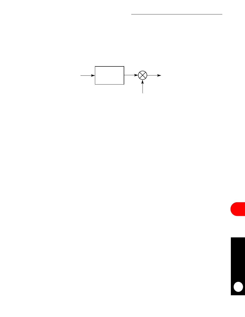
Figure 16-10 illustrates an example section of a V.32 modem’s transmit (TX) data pump
flow. The TX filter is composed of three FIR2 subfilters.
To implement this DSP task with C code on the core, it takes 476 core instructions (371 for
the filter and 105 for the modulation) to execute the code. Repeating that 2,400 times a
second consumes 1.14MIPS (476 x 2,400) of the core. To implement a task using the CPM
functions, the software builds a static function descriptor structure composed of two chained
functions—a FIR2 and a MOD. The core activates the RISC microcontroller to execute those
functions by sending a single write to the CPM command register. Using an interrupt, the
communication processor module then signals that the process has completed. The
communication processor module executes the functions twice as efficiently as the core,
which results in 0.55 CPM MIPS and very few core cycles.
The TX filter is implemented by executing three subfilters each time a new sample is
received. This is accomplished by invoking FIR2 with a three-iteration count and
autoincrement of the input sample pointer when the function is completed. FIR2 writes the
three results into the output buffer, which is also the modulation input buffer. Modulation is
accomplished by invoking MOD with a three-iteration count. The input pointer is
autoincremented with each iteration.
Figure 16-10. DSP Implementation Example
MODULATION
TX FILTER
COS WT, SIN WT
1 INPUT / BAUD 3 OUTPUTS / BAUD 3 OUTPUTS / BAUD



 To Next Page