Communication Processor Module
MOTOROLA
MPC823e REFERENCE MANUAL
16-79
COMMUNICATION
16
PROCESSOR MODULE
TIMERS
FRR—Free Run/Restart
0 = Free run. The timer count continues to increment after the reference value is
reached.
1 = Restart. The timer count is reset immediately after the reference value is reached.
ICLK—Input Clock Source for the Timer
00 = Internally cascaded input.
For TMR1, the timer 1 input is the output of timer 2.
For TMR3, the timer 3 input is the output of timer 4.
For TMR2 and TMR4, this selection means no input clock is provided to the timer.
01 = Internal general system clock.
10 = Internal general system clock divided by 16.
11 = Corresponding TINx pin (falling edge).
GE—Gate Enable
0 = The TGATE1
signal is ignored.
1 = The TGATE1
signal is used to control the timer.
16.4.2.4 TIMER REFERENCE REGISTERS.
Each of the 16-bit, memory-mapped,
read/write timer reference registers (TRR1–TRR4) contain the timeout’s reference value.
REFERENCE—Reference to TCNx
This reference value is reached when the TCNx register increments to equal the TRRx
register.
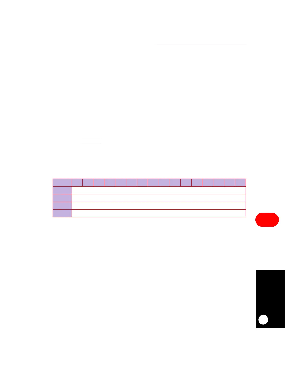
TRR1–TRR4
BIT
0 1 2 3 4 5 6 7 8 9 10 11 12 13 14 15
FIELD
REFERENCE
RESET
1
R/W
R/W
ADDR
(IMMR & 0xFFFF0000) + 0x994 (TRR1), 0x996 (TRR2), 0x9A4 (TRR3), 0x9A6 (TRR4)