Communication Processor Module
16-80
MPC823e REFERENCE MANUAL
MOTOROLA
TIMERS
COMMUNICATION
16
PROCESSOR MODULE
16.4.2.5 TIMER CAPTURE REGISTERS.
Each of the 16-bit, memory-mapped, read-only
timer capture registers (TCR1–TCR4) are used to latch the value of the counter at the falling
edge of every TINx signal. The CE field in the TMRx register defines whether the counter
starts at the rising or falling edge of the TINx signal.
CAPTURE COUNT
This field contains the value of the timer counter register at the falling edge of the TINx
signal.
16.4.2.6 TIMER COUNTER REGISTERS.
Each of the 16-bit, memory-mapped, read/write
timer counter (TCN1 and TCN4) registers are up-counters. In timer capture mode, the TINx
signal defines when the counter begins. A read to TCNx yields the current value of the timer,
but does not affect the counting operation. A write to TCNx sets the register to that value,
which causes the corresponding prescaler in the PS field of the TMRx register to be reset.
COUNT—Counter Value
This represents the value of the counter.
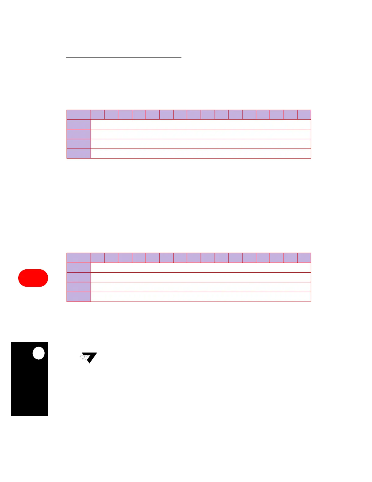
TCR1–TCR4
BIT
0 1 2 3 4 5 6 7 8 9 10 11 12 13 14 15
FIELD
CAPTURE COUNT
RESET
0
R/W
R
ADDR
(IMMR & 0xFFFF0000) + 0x998 (TCR1), 0x99A (TCR2), 0x9A8 (TCR3), 0x9AA (TCR4)
TCN1–TCN4
BIT
0 1 2 3 4 5 6 7 8 9 10 11 12 13 14 15
FIELD
COUNT
RESET
—
R/W
R/W
ADDR
(IMMR & 0xFFFF0000) + 0x99C (TCN1), 0x99E (TCN2), 0x9AC (TCN3), 0x9AE (TCN4)
NOTE: — = Undefined.
Note:
The TCNx register may not be updated correctly if a write is made to it while the
timer is not running. You must always use the TRRx register to define the
preferred counter value.