Communication Processor Module
MOTOROLA
MPC823e REFERENCE MANUAL
16-87
SDMA
COMMUNICATION
16
PROCESSOR MODULE
16.5.2.2 SDMA STATUS REGISTER. Shared by all 12 SDMA channels, the 8-bit
memory-mapped SDMA status register (SDSR) is used to report events recognized by the
SDMA controller. When an event is recognized, the SDMA sets the corresponding bit in the
SDSR. A bit is reset by writing a 1 (writing a zero has no effect) and more than one bit can
be reset at a time. This register is cleared by reset and can be read at any time.
SBER—SDMA Channel Bus Error (SDMA function)
This bit indicates that an error caused the SDMA channel to be terminated during a read or
write cycle. The SDMA bus error address can be read from the SDMA address register.
Bits 1–5—Reserved
These bits are reserved and must be set to 0.
DSP2—DSP Chain 2 Transmitter Interrupt (DSP function)
This bit is set when the chain 2 function finishes executing. However, the I bit must be set in
the function descriptor, as described in Section 16.3.3.3 DSP Event Register.
DSP1—DSP Chain 1 Receiver Interrupt (DSP function)
This bit is set when the chain 1 function finishes executing. However, the I bit must be set in
the function descriptor, as described in Section 16.3.3.3 DSP Event Register.
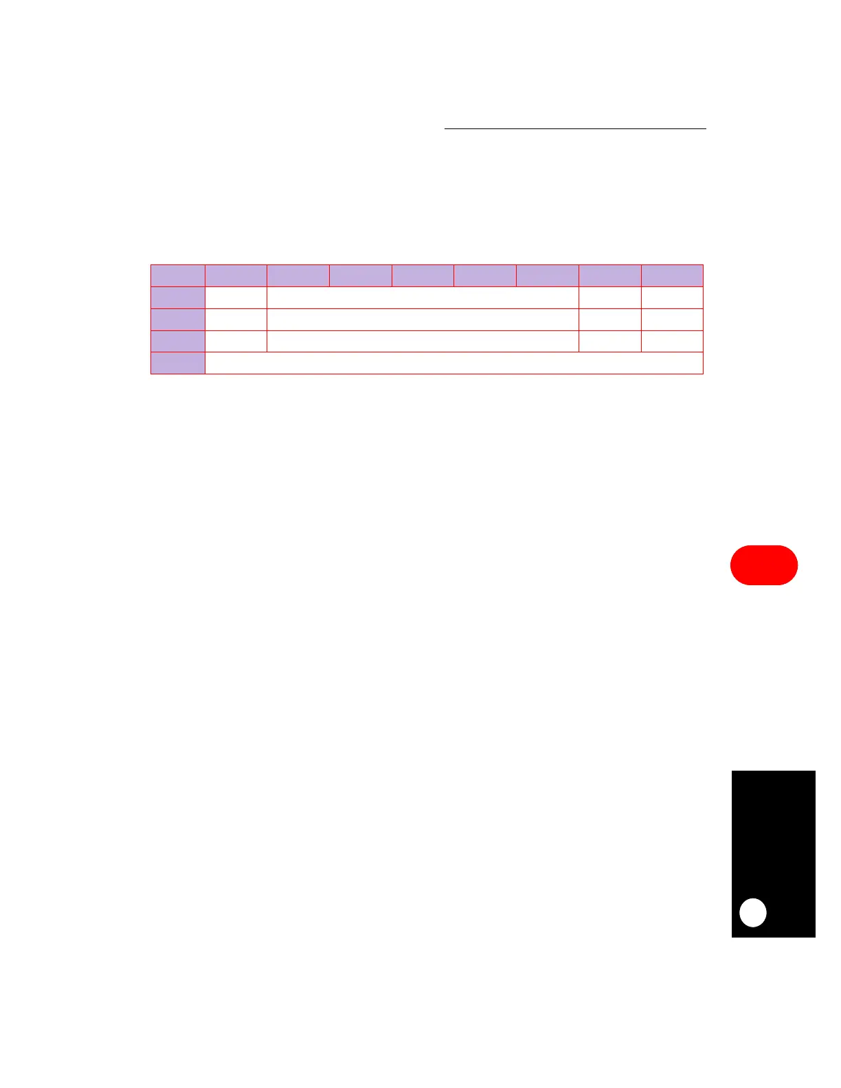
SDSR
BIT 0 1 2 3 4 5 6 7
FIELD SBER RESERVED DSP2 DSP1
RESET 0000
R/W R/W R/W R/W R/W
ADDR (IMMR & 0xFFFF0000) + 0x908