Communication Processor Module
MOTOROLA MPC823e REFERENCE MANUAL 16-91
IDMA
COMMUNICATION
16
PROCESSOR MODULE
Follow these steps to perform an IDMA transfer:
1. Define the source (peripheral) address to be burst aligned.
2. Define the destination address to be burst aligned.
3. Program the IDMA mode register (DCMR) to 0x0000.
16.6.3.1 AUTOBUFFER AND BUFFER CHAINING. The host CPU must initialize the
IDMA buffer descriptor ring with the appropriate buffer handling mode, source address,
destination address, and block length.
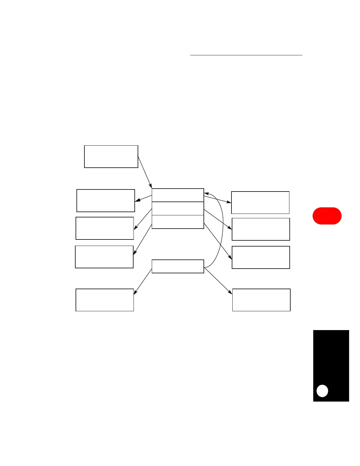
The data associated with each IDMA channel for autobuffer and buffer chaining modes is
stored in buffers and each buffer is referenced by a buffer descriptor that uses a ring
structure located in the dual-port RAM.
Figure 16-38. IDMA Buffer Descriptor Ring
IDMA BD BASE
BD 0
BD 1
BD 2
BD N
SOURCE DEVICE OR
DATA BUFFER 0
SOURCE DEVICE OR
DATA BUFFER 1
SOURCE DEVICE OR
DATA BUFFER 2
SOURCE DEVICE OR
DATA BUFFER N
DESTINATION DEVICE
OR DATA BUFFER 0
DESTINATION DEVICE
OR DATA BUFFER 1
DESTINATION DEVICE
OR DATA BUFFER 2
DESTINATION DEVICE
OR DATA BUFFER N
ADDRESS (IBASE)
•
•
•
 Loading...

