Communication Processor Module
16-92 MPC823e REFERENCEMANUAL MOTOROLA
IDMA
COMMUNICATION
16
PROCESSOR MODULE
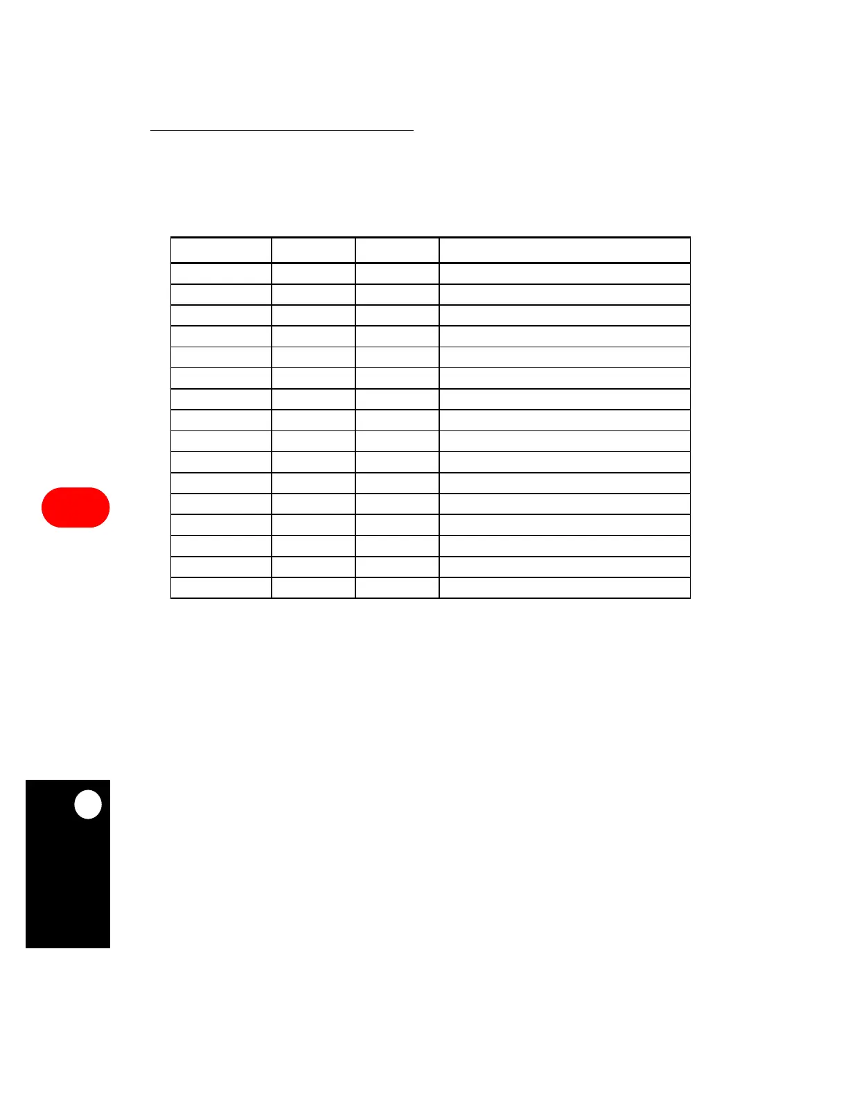
16.6.3.2 IDMA PARAMETER RAM MEMORY MAP. The MPC823e uses the IDMA
parameters listed in the table below to configure the IDMA channel for autobuffer or buffer
chaining mode.
• IBASE—This index pointer defines the starting point in the dual-port RAM for the set of
IDMA buffer descriptors. It is an offset from the beginning of the dual-port RAM. You
must initialize this entry before enabling the IDMA channel and if you overlap the buffer
descriptor tables of two enabled serial channels or IDMA channels, erratic behavior will
occur. IBASE must contain a value that is divisible by 16.
Table 16-21. IDMA Parameter RAM Memory Map
ADDRESS NAME WIDTH DESCRIPTION
IDMA Base + 00 IBASE Half-word IDMA Buffer Descriptor Base Address Index Pointer
IDMA Base + 02 DCMR Half-word IDMA Channel Mode Register
IDMA Base + 04 SAPR Word Source Internal Address Pointer
IDMA Base + 08 DAPR Word Destination Internal Address Pointer
IDMA Base + 0C IBPTR Half-word Buffer Descriptor Pointer
IDMA_Base +0E WRITE_SP Half-word —
IDMA Base + 10 S_BYTE_C Word Internal Source Byte Count
IDMA Base + 14 D_BYTE_C Word Internal Destination Byte Count
IDMA Base + 18 S_STATE Word Internal State
IDMA Base + 1C ITEMP Four-word Temporary Data Storage
IDMA Base + 2C SR_MEM Word Data Storage for Peripheral Write
IDMA Base + 30 READ_SP Half-word —
IDMA Base + 32 — Half-word Difference Between Source and Destination Residue
IDMA Base + 34 — Half-word Temporary Storage Address Pointer
IDMA Base + 36 — Half-word SR_MEM Byte Count
IDMA Base + 38 D_STATE Word Internal State
NOTE:
You are only responsible for initializing the items in bold.
IDMA Base = (IMMR & 0xFFFF0000) + 0x3CC0 (IDMA1) or 0x3DC0 (IDMA2).
All references to registers in the parameter RAM table are actually implemented in the dual-port RAM
area as a memory-based register.
 Loading...

