Communication Processor Module
16-164
MPC823e REFERENCE MANUAL
MOTOROLA
SCCs
COMMUNICATION
16
PROCESSOR MODULE
Each internal clock of a serial communication controller can be programmed with either an
external or internal source. The internal clocks originate from one of four baud rate
generators or one of four external clock pins. These clocks can be as fast as a 1:2 ratio of a
12.5MHz system clock. However, a serial communication controller’s ability to support a
sustained bitstream depends on the protocol, as well as other factors. Associated with each
serial communication controller is a digital phase-locked loop (DPLL) for external clock
recovery (NRZ, NRZI, FM0, FM1, Manchester, and Differential Manchester). The DPLL can
be configured to NRZ operation to pass the clocks and data to or from a serial
communication controller without modifying it.
The RISC microcontroller is responsible for selecting and controlling the various ports and
controllers of the communication processor module. For information about the serial
communication controller command set, see Table 16-2.
A serial communication controller can be connected to its own set of pins on the MPC823e.
This configuration is called the nonmultiplexed serial interface (NMSI) and is described in
Section 16.7 The Serial Interface with Time-Slot Assigner
. In this configuration, a serial
communication controller can support the standard modem interface signals—RTSx
, CTSx,
and CDx
—through the Port B, Port C and CPM interrupt controller pins. Additional
handshake signals can be supported with additional parallel I/O lines. The serial
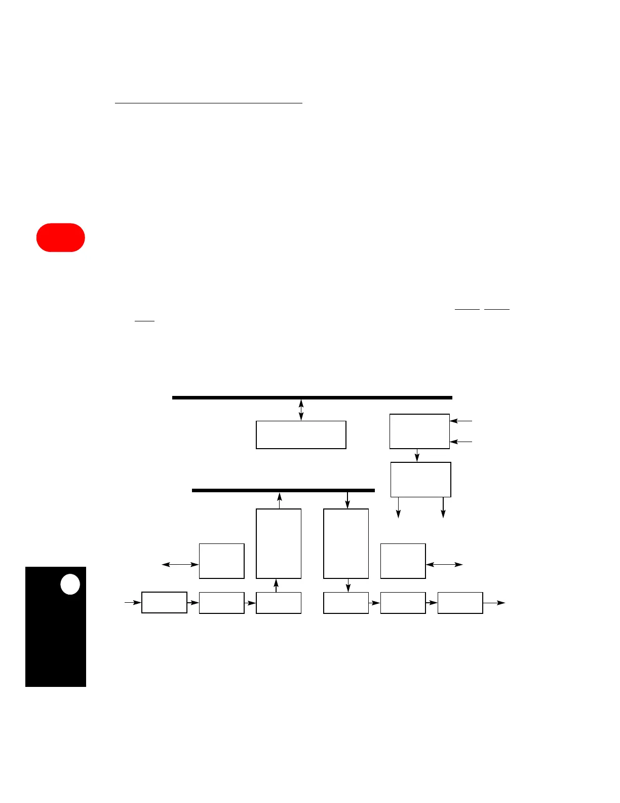
communication controller block diagram is illustrated in Figure 16-64.
Figure 16-64. Serial Communication Controller Block Diagram
CONTROL
REGISTERS
DPLL
AND CLOCK
SHIFTERSHIFTER DELIMITER
CLOCK
GENERATOR
DELIMITER
DECODER
ENCODER
RECOVERY
RECEIVE
CONTROL
UNIT
TRANSMIT
CONTROL
UNIT
RECEIVE
DATA
FIFO
TRANSMIT
DATA
FIFO
MODEM LINES
MODEM LINES
U-BUS
PERIPHERAL BUS
TCLK
RCLK
INTERNAL CLOCKS
RXDx
TXDx