Communication Processor Module
MOTOROLA MPC823e REFERENCE MANUAL 16-179
SCCs
COMMUNICATION
16
PROCESSOR MODULE
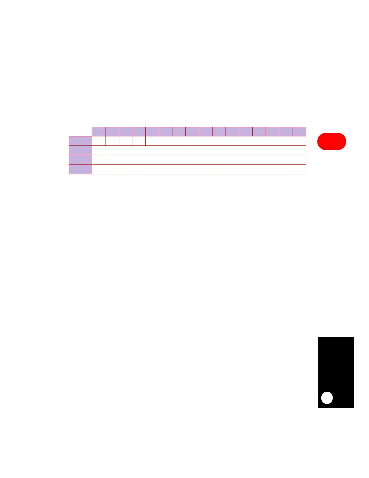
The format of the buffer descriptors is the same for each serial communication controller
mode of operation and for transmit and receive. The first word in each buffer descriptor
contains a status and control word that determines the buffer descriptor’s table length. Only
this first field, which contains the status and control bits, differs for each protocol. The
second word determines the data length referenced to this buffer descriptor and the last two
words in the buffer descriptor contain a 32-bit address pointer that points to the actual buffer
in memory.
R/E—Ready/Empty
Ready (Transmitter):
0 = The data buffer associated with this buffer descriptor is not ready to be transmitted.
You are free to manipulate this buffer descriptor or its associated data buffer. The
communication processor module clears this bit after the buffer is transmitted or
after an error condition is encountered.
1 = The data buffer, which you must prepare for transmission, has not been
transmitted yet or is currently being transmitted. You cannot write any fields of this
buffer descriptor once this bit is set.
Empty (Receiver):
0 = The data buffer associated with this RX buffer descriptor has been filled with data
or reception has been aborted because of an error condition. The core is free to
examine or write to any fields of this RX buffer descriptor. The communication
processor module does not use this buffer descriptor again as long as the E bit is
zero.
1 = The data buffer associated with this buffer descriptor is empty or is currently
receiving data. This RX buffer descriptor and its associated receive buffer are
owned by the communication processor module. Once the E bit is set, the core
must not write any fields of this RX buffer descriptor.
W—Wrap
0 = This is not the last buffer descriptor in the buffer descriptor ring.
1 = This is the last buffer descriptor in the buffer descriptor ring. After this buffer has
been used, the communication processor module will transmit (receive) data from
the first buffer descriptor that TBASE (RBASE) points to in the table. The number
of TX buffer descriptors in the ring are programmable and determined only by the
W bit and overall space constraints of the dual-port RAM.
0 1 2 3 4 5 6 7 8 9 10 11 12 13 14 15
OFFSET + 0
R/E — W I STATUS AND CONTROL
OFFSET + 2
DATA LENGTH
OFFSET + 4
HIGH-ORDER DATA BUFFER POINTER
OFFSET + 6
LOW-ORDER DATA BUFFER POINTER