External Signals
2-6
MPC823e REFERENCE MANUAL
MOTOROLA
EXTERNAL SIGNALS
2
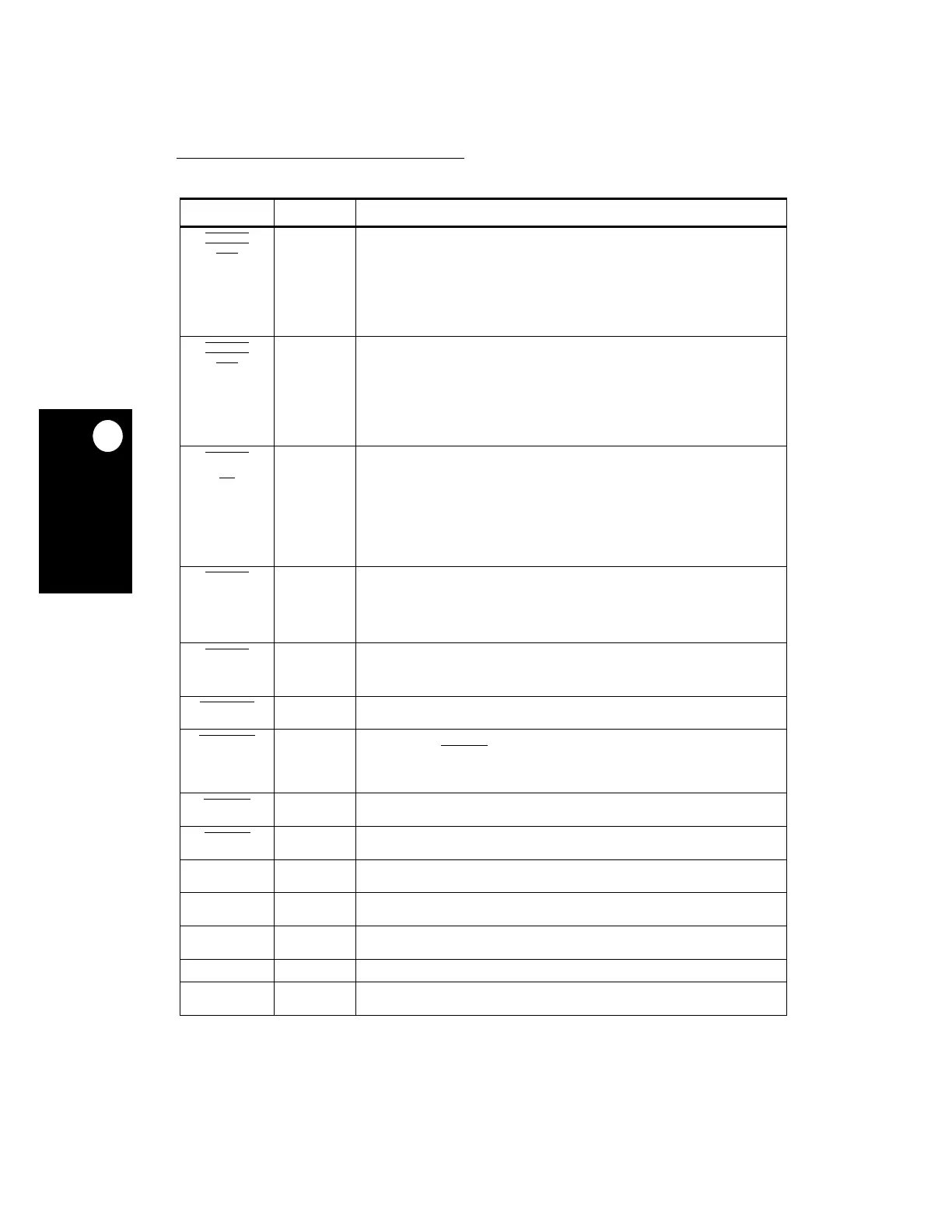
GPL_A
2
GPL_B2
CS2
C15
General-Purpose Line 2 on UPMA
—This output signal reflects the value specified
in the UPMA in the memory controller when an external transfer to a slave is
controlled by the user programmable machine A (UPMA).
General-Purpose Line 2 on UPMB
—This output signal reflects the value specified
in the UPMB in the memory controller when an external transfer to a slave is
controlled by the user programmable machine B (UPMB).
Chip Select
2
—This output signal enables a peripheral or memory device at a
programmed address if defined appropriately in the BR2 and OR2 registers of the
memory controller.
GPL_A
3
GPL_B3
CS3
D14
General-Purpose Line 3 on UPMA
—This output signal reflects the value specified
in the UPMA in the memory controller when an external transfer to a slave is
controlled by the user programmable machine A (UPMA).
General-Purpose Line 3 on UPMB
—This output signal reflects the value specified
in the UPMB in the memory controller when an external transfer to a slave is
controlled by the user programmable machine B (UPMB).
Chip Select
3
—This output signal enables a peripheral or memory device at a
programmed address if defined appropriately in the BR3 and OR3 registers of the
memory controller.
GPL_A4
UPWAITA
AS
D11
General-Purpose Line 4 on UPMA
—This output signal reflects the value specified
in the UPMA in the memory controller when an external transfer to a slave is
controlled by the user programmable machine A (UPMA).
User Programmable Machine Wait A
—This input signal is sampled when you need
it and when an access to an external slave is controlled by the UPMA in the memory
controller.
Address Strobe
—This input pin is driven by an external asynchronous master to
indicate a valid address on the A[6:31] lines. The memory controller in the MPC823e
will synchronize this signal and control the memory device addressed if it is
recognized to be under its control.
GPL_B
4
UPWAITB
B13
General-Purpose Line 4 on UPMB
—This output signal reflects the value specified
in the UPMB in the memory controller when an external transfer to a slave is
controlled by the user programmable machine B (UPMB).
User Programmable Machine Wait B
—This input signal is sampled when you need
it and when an access to an external slave is controlled by the UPMB in the memory
controller.
GPL_A5
C12
General-Purpose Line 5 on UPMA
—This output signal reflects the value specified
in the UPMA in the memory controller when an external transfer to a slave is
controlled by the user programmable machine A (UPMA). This signal can also be
controlled by the UPMB.
PORESET
B3
Power-On Reset
—When asserted, this input signal causes the MPC823e to enter
the power-on reset state.
RSTCONF
C5
Reset Configuration
—This input signal is sampled by the MPC823e during the
assertion of the HRESET
signal. If it is asserted, the configuration mode is sampled
in the form of the hard reset configuration word driven on the data bus. When this
signal is negated, the default configuration mode is adopted by the MPC823e. Notice
that the initial base address of internal registers is determined in this sequence.
HRESET
B5
Hard Reset
—This open drain line, when asserted, causes the MPC823e to enter the
hard reset state.
SRESET
B4
Soft Reset
—This open drain line, when asserted, causes the MPC823e to enter the
soft reset state.
XTAL A4
External Crystal
—This output signal is one of the connections to an external crystal
for the internal oscillator circuitry.
EXTAL A5
External Crystal
—This signal is one of the connections to an external crystal for the
internal oscillator circuitry.
XFC B2
External Filter Capacitance
—This input signal is the connection pin to an external
capacitor filter for the PLL circuitry.
CLKOUT D1
CLKOUT
—This output signal is the clock system frequency.
EXTCLK A6
External Clock
—This input signal is the external input clock from an external
source.
Table 2-1. Signal Descriptions (Continued)
SIGNAL PIN NUMBER DESCRIPTION