External Signals
MOTOROLA MPC823e REFERENCE MANUAL 2-11
EXTERNAL SIGNALS
2
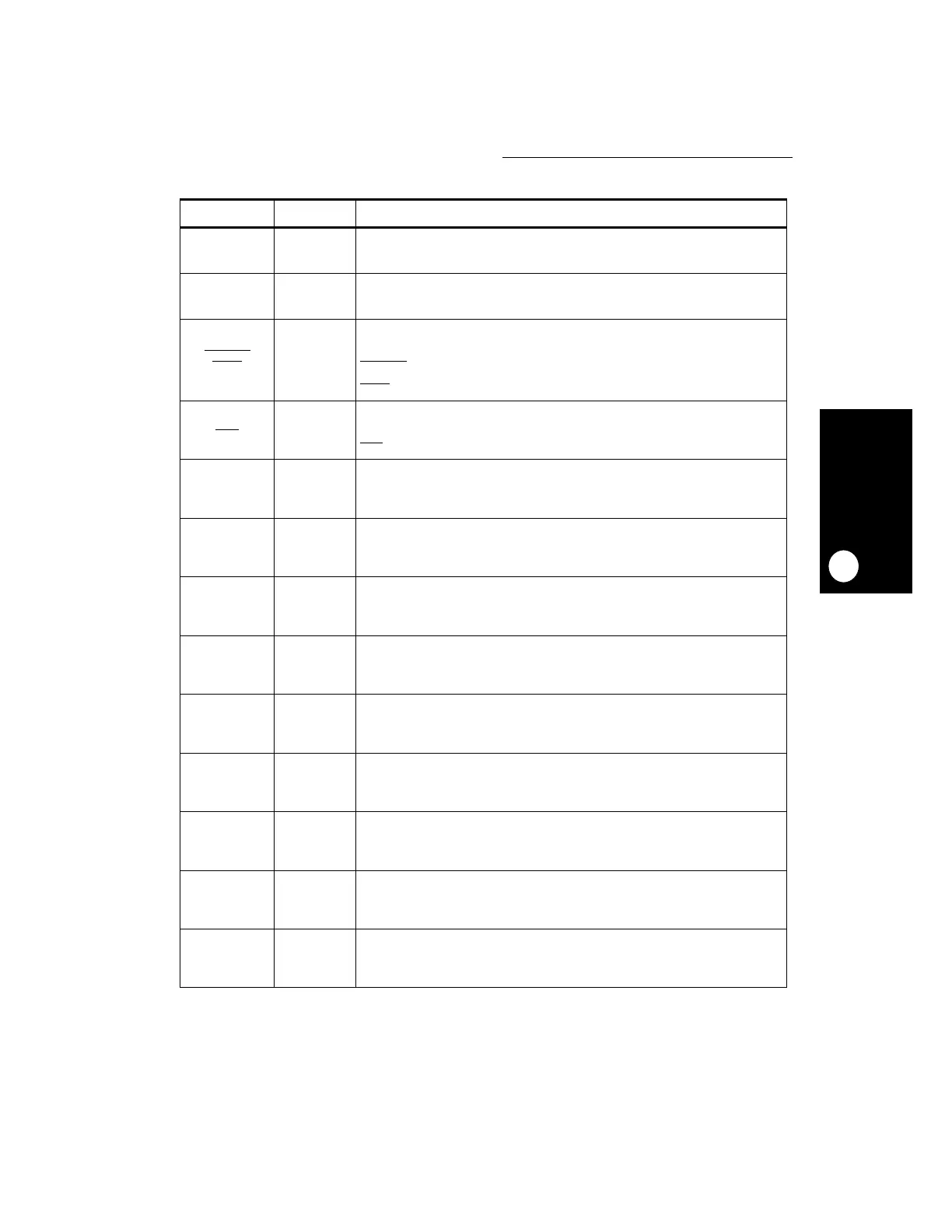
PC[7]
USBTXP
T5 General-Purpose I/O Port C Bit 7—Bit 7 of the general-purpose I/O port C.
USBTXP—This output signal, in conjunction with USBTXN, are the transmit lines of
the USB.
PC[6]
USBTXN
N6 General-Purpose I/O Port C Bit 6—Bit 6 of the general-purpose I/O port C.
USBTXN—This output signal, in conjunction with USBTXP, are the transmit lines of
the USB.
PC[5]
L1TSYNCA
SDACK1
CTS3
P6 General-Purpose I/O Port C Bit 5—Bit 5 of the general-purpose I/O port C.
L1TSYNCA—The transmit sync input for the serial interface time-division multiplex
port A.
SDACK1
—The SDMA acknowledge 1output pin that is used as a peripheral
interface signal for IDMA emulation.
CTS3—The Clear to Send Modem line for serial communication controller 3.
PC[4]
L1RSYNCA
CD3
T4 General-Purpose I/O Port C Bit 4—Bit 4 of the general-purpose I/O port C.
L1RSYNCA—The receive sync input for the serial interface time-division multiplex
port A.
CD3
—The Carrier Detect Modem line for serial communication controller 3.
PD[15]
LD8
VD7
R4 General-Purpose I/O Port D Bit 15—Bit 15 of the general-purpose I/O port D.
LD8—One of the 12 data bus bits used to drive the LCD panel.
VD7—One of the data bus bits of the video controller used for driving the video
encoder.
PD[14]
LD7
VD6
T3 General-Purpose I/O Port D Bit 14—Bit 14 of the general-purpose I/O port D.
LD7—One of the 12 data bus bits used to drive the LCD panel.
VD6—One of the data bus bits of the video controller used for driving the video
encoder.
PD[13]
LD6
VD5
P5 General-Purpose I/O Port D Bit 13—Bit 13 of the general-purpose I/O port D.
LD6—One of the 12 data bus bits used to drive the LCD panel.
VD5—One of the data bus bits of the video controller used for driving the video
encoder.
PD[12]
LD5
VD4
R3 General-Purpose I/O Port D Bit 12—Bit 12 of the general-purpose I/O port D.
LD5—One of the 12 data bus bits used to drive the LCD panel.
VD4—One of the data bus bits of the video controller used for driving the video
encoder.
PD[11]
LD4
VD3
N5 General-Purpose I/O Port D Bit 11—Bit 11 of the general-purpose I/O port D.
LD4—One of the 12 data bus bits used to drive the LCD panel.
VD3—One of the data bus bits of the video controller used for driving the video
encoder.
PD[10]
LD3
VD2
T2 General-Purpose I/O Port D Bit 10—Bit 10 of the general-purpose I/O port D.
LD3—One of the 12 data bus bits used to drive the LCD panel.
VD2—One of the data bus bits of the video controller used for driving the video
encoder.
PD[9]
LD2
VD1
P4 General-Purpose I/O Port D Bit 9—Bit 9 of the general-purpose I/O port D.
LD2—One of the 12 data bus bits used to drive the LCD panel.
VD1—One of the data bus bits of the video controller used for driving the video
encoder.
PD[8]
LD1
VD0
T1 General-Purpose I/O Port D Bit 8—Bit 8 of the general-purpose I/O port D.
LD1—One of the 12 data bus bits used to drive the LCD panel.
VD0—One of the data bus bits of the video controller used for driving the video
encoder.
PD[7]
LD0
FIELD
R2 General-Purpose I/O Port D Bit 7—Bit 7 of the general-purpose I/O port D.
LD0—One of the 12 data bus bits used to drive the LCD panel.
FIELD—The line the video controller uses to signal which of the two fields is the
current one.
Table 2-1. Signal Descriptions (Continued)
SIGNAL PIN NUMBER DESCRIPTION