Communication Processor Module
16-292
MPC823e REFERENCE MANUAL
MOTOROLA
COMMUNICATION
16
SCCs
The link layer frame generally consists of the address, control, data and CRC32 fields. The
IrDA transmitter decodes the packet bits into 4PPM format. The 4PPM encoding will be
described later. The receiver is responsible to decode the incoming data frame into the
regular bit format and to deliver it to the software. The receiver continues to receive and
interpret data until the stop flag (STO) is recognized. A stop flag indicates the end of frame.
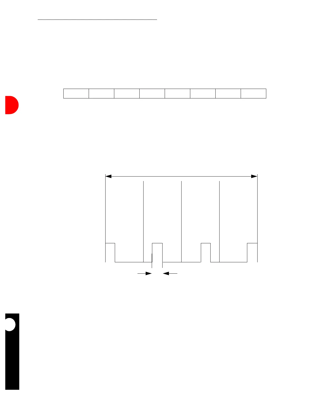
The stop flag consists of exactly one transmission of the following stream of symbols.
The physical layer defines the electrical parameters of the signals between the
encoder/decoder module and the IR transducer module. All frame envelope
patterns—PA, STA, and STO—are transmitted as is. The link layer frame bits are encoded
before transmission. Each two bits encoded into four chips according to the 4PPM scheme.
Figure 16-101. Stop Flag Symbol Format
Figure 16-102. High-Speed IrDA Data Format
0000 1100 0000 1100 0000 1100 0000 1100
00011011
DATA BITS
1/4 BIT TIME
(A)
(B)
 Loading...

