Communication Processor Module
MOTOROLA MPC823e REFERENCE MANUAL 16-431
SMC
COMMUNICATION
16
PROCESSOR MODULE
16.11.8.4 SMCx GCI MODE REGISTER. When a serial management controller is in GCI
mode, the 16-bit, memory-mapped, read/write SMCx mode register is referred to as the
SMCx GCI mode (SMCM–GCI) register. The functions of bits 8–15 are common to each
SMCx protocol, but bits 0–7 vary according to the protocol selected by the SM bits.
Bits 0, 6, and 8–9—Reserved
These bits are reserved and must be set to 0.
CLEN—Character Length
This field is used to define the total number of bits in the circuit interface and monitor
channels of the SCIT channels 0 or 1. CLEN ranges from 0 to 15 and specifies values from
1 to 16 bits. CLEN must be written with 13 for the SCIT channel 0 or GCI (8 data bits, plus
A and E bits, plus 4 circuit interface bits = 14 bits) or with 15 for the SCIT channel 1 (8 data,
bits, plus A and E bits, plus 6 circuit interface bits = 16 bits).
ME—Monitor Enable
0 = The serial management controller does not support the monitor channel.
1 = The serial management controller supports the monitor channel with the monitor
channel protocol.
C#—SCIT Channel Number
0 = SCIT channel 0.
1 = SCIT channel 1. Required for Siemens ARCOFI and SGS S/T chips.
SM—SMCx Mode
00 = GCI or SCIT mode. Required for SMCx GCI or SCIT operation.
01 = Reserved.
10 = UART mode.
11 = Totally transparent mode.
DM—Diagnostic Mode
00 = Normal mode.
01 = Local loopback mode.
10 = Echo mode.
11 = Reserved.
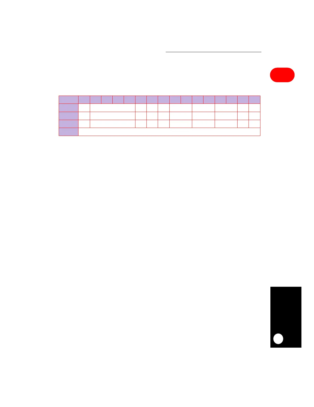
SMCM–GCI
BIT 0 1 2 3 4 5 6 7 8 9 10 11 12 13 14 15
FIELD RES CLEN ME RES C# RES SM DM TEN REN
RESET 0 0 000 0 0 0 00
R/W R/W R/W R/W R/W R/W R/W R/W R/W R/W R/W
ADDR (IMMR & 0xFFFF0000) + 0xA82 (SMCMR1), 0xA92 (SMCMR2)
 Loading...

