Communication Processor Module
16-468 MPC823e REFERENCE MANUAL MOTOROLA
I
2
C
COMMUNICATION
16
PROCESSOR MODULE
16.13.7 Programming the I
2
C Controller
16.13.7.1 I
2
C MODE REGISTER. The read/write I
2
C mode (I2MOD) register controls both
the I
2
C operation mode and clock source.
Bits 0–1—Reserved
These bits are reserved and must be set to 0.
REVD—Reverse Data
This bit determines the receive and transmit character bit order.
0 = Normal operation. Most-significant bit of character transmitted and received first.
1 = Reverse data. Least-significant bit of character transmitted and received first.
GCD—General Call Disable
This bit determines if the receiver will acknowledge a general call address.
0 = General call address is enabled.
1 = General call address is disabled.
FLT—Clock Filter
This bit determines if the I
2
C input clock is filtered to prevent spikes in a noisy environment.
0 = I2CLK is not filtered.
1 = I2CLK is filtered by a digital filter.
PDIV—Pre Divider
This field determines the division factor of the clock before it is fed into the baud rate
generator. The clock source for the I
2
C controller is the BRGCLK that is generated by the
system interface unit.
00 = Use the BRGCLK/32 as the input to the I
2
C baud rate generator.
01 = Use the BRGCLK/16 as the input to the I
2
C baud rate generator.
10 = Use the BRGCLK/8 as the input to the I
2
C baud rate generator.
11 = Use the BRGCLK/4 as the input to the I
2
C baud rate generator.
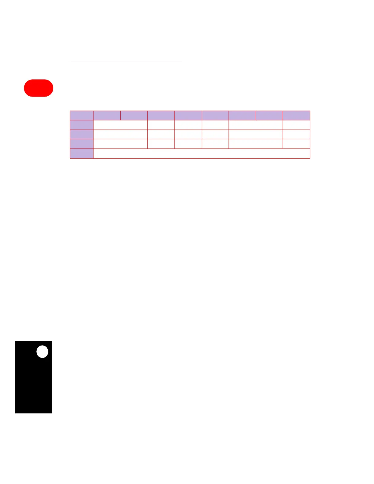
I2MOD
BIT 0 1 2 3 4 5 6 7
FIELD RESERVED REVD GCD FLT PDIV EN
RESET 000000
R/W R/W R/W R/W R/W R/W R/W
ADDR (IMMR & 0xFFFF0000) + 0x860