Communication Processor Module
MOTOROLA MPC823e REFERENCE MANUAL 16-473
I
2
C
COMMUNICATION
16
PROCESSOR MODULE
DATA LENGTH
This field represents the number of octets the communication processor module must
transmit from this buffer descriptor data buffer. However, it is never modified by the
communication processor module. Normally, this value must be greater than zero. The I
2
C
controller writes these bits after it finishes transmitting the associated data buffer.
TX DATA BUFFER POINTER
This field always points to the first location of the associated data buffer. They can be even
or odd, unless the number of actual data bits in the character is greater than 8 bits, in which
case the transmit buffer pointer must be even. The buffer can reside in internal or external
memory. The I
2
C controller writes these bits after it finishes transmitting the associated data
buffer.
16.13.7.4 I
2
C ADDRESS REGISTER. The 8-bit, memory-mapped, read/write I
2
C address
(I2ADD) register holds the address for this I
2
C port. You must program this register if you
are operating in multimaster, slave, or local loopback mode. You must clear this register
before using I
2
C Master Mode. If you do not, this register may cause the I
2
C controller to
match the address of an external device, thus causing incorrect behavior.
SAD— Slave Address 0–6
This field holds the slave address for the I
2
C port.
Bit 7—Reserved
This bit is reserved and must be set to 0.
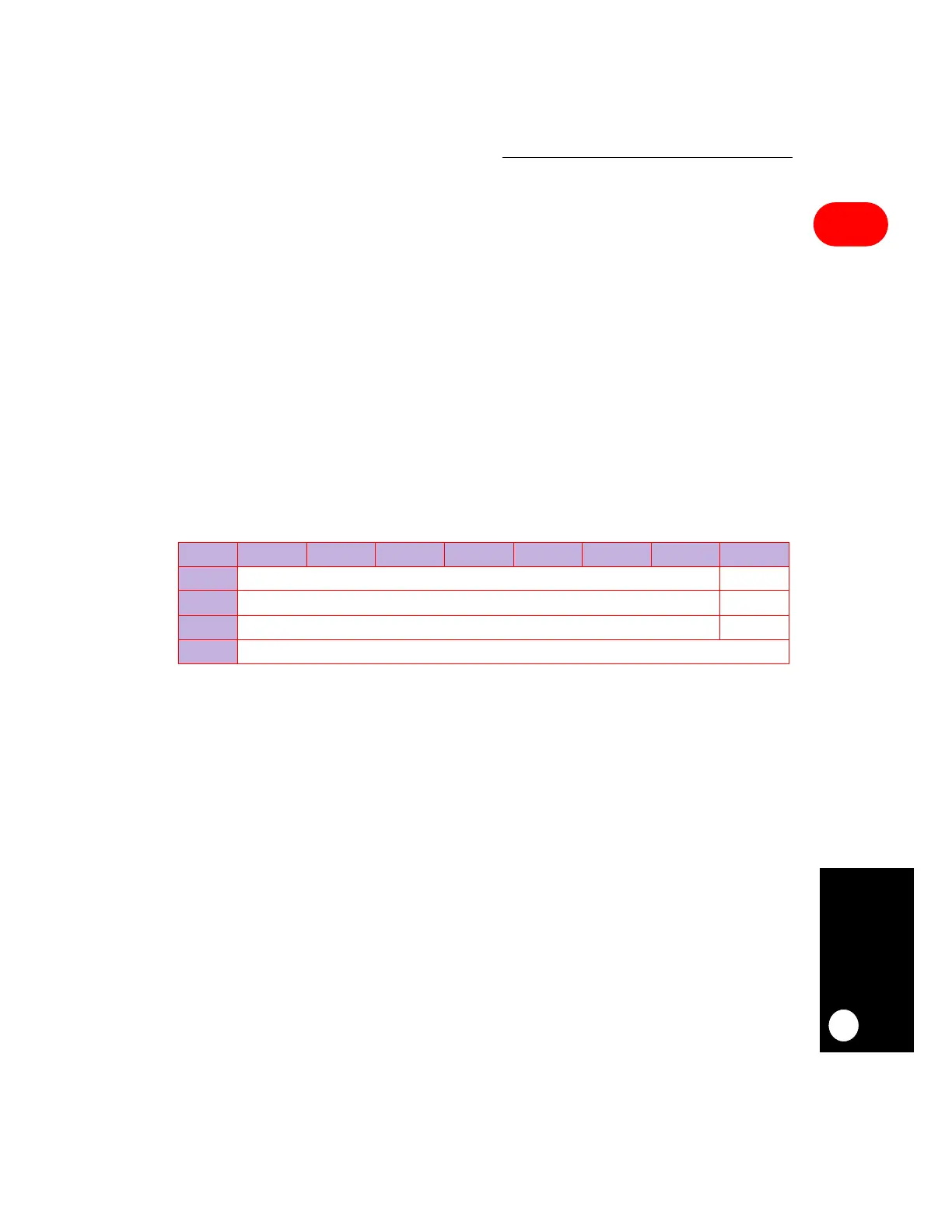
I2ADD
BIT 0 1 2 3 4 5 6 7
FIELD SAD RESERVED
RESET 00
R/W R/W R/W
ADDR (IMMR & 0xFFFF0000) + 0x864
NOTE:
—
= Undefined.