Communication Processor Module
16-474 MPC823e REFERENCE MANUAL MOTOROLA
I
2
C
COMMUNICATION
16
PROCESSOR MODULE
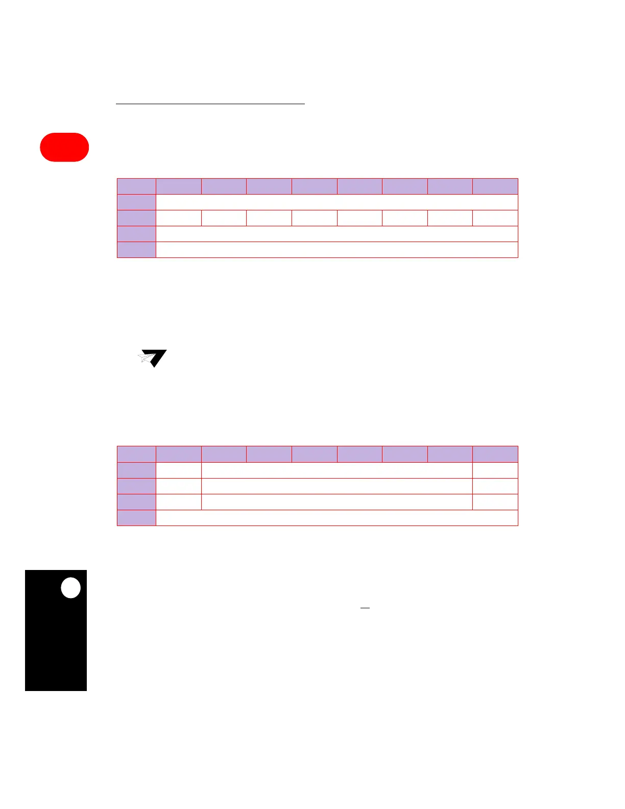
16.13.7.5 I
2
C BAUD RATE GENERATOR REGISTER. The 8-bit, memory mapped,
read/write I
2
C baud rate generator (I2BRG) register sets the divide ratio of the baud rate
generator. This register is set to all ones at hard reset.
DIV— Division Ratio 0–7
This field specifies the divide ratio of the baud rate generator divider in the I
2
C clock
generator. The output of the prescaler is divided by 2 x (DIV + 3 + (2 x FLT)) and the clock
has a 50% duty cycle. The FLT bit is in the I2MOD register.
16.13.7.6 I
2
C COMMAND REGISTER. The 8-bit read/write I
2
C command (I2COM) register
is used to start I
2
C operation.
STR—Start Transmit
When the I
2
C controller is in master mode, setting this bit to 1 causes the I
2
C controller to
start transmitting data from the I
2
C transmit buffers if they are ready. When the I
2
C controller
is in slave mode, setting the STR bit to 1 when the I
2
C controller is idle causes it to load the
transmit data register from the I
2
C transmit buffer and start transmitting when it receives an
address byte that matches the slave address with the R/W
bit set to 1. The STR bit is always
read as a zero.
I2BRG
BIT 0 1 2 3 4 5 6 7
FIELD DIV
RESET 11111111
R/W R/W
ADDR (IMMR & 0xFFFF0000) + 0x868
Note: The minimum value for DIV is three if the digital filter is disabled (FLT=0) and six
if it is enabled (FLT=1).
I2COM
BIT 0 1 2 3 4 5 6 7
FIELD STR RESERVED M/S
RESET 000
R/W R/W R/W R/W
ADDR (IMMR & 0xFFFF0000) + 0x86C