Communication Processor Module
MOTOROLA MPC823e REFERENCE MANUAL 16-475
I
2
C
COMMUNICATION
16
PROCESSOR MODULE
Bits 1–6—Reserved.
These bits are reserved and must be set to 0.
M/S—Master/Slave
This bit configures the I
2
C controller to operate as a master or a slave.
0 = I
2
C controller is a slave.
1 = I
2
C controller is a master.
16.13.7.7 I
2
C EVENT REGISTER. The 8-bit memory-mapped I
2
C event register (I2CER) is
used to generate interrupts and report events recognized by the I
2
C controller. When an
event is recognized, the I
2
C controller sets its corresponding bit in the I2CER. Interrupts
generated by this register can be masked in the I
2
C mask register. A bit is cleared by writing
a 1 (writing a zero has no effect) and more than one bit can be cleared at a time. All
unmasked bits must be cleared before the communication processor module clears the
internal interrupt request. This register is cleared by reset and can be read at any time.
Bits 0–2 and 4—Reserved
These bits are reserved and must be set to 0.
TXE—TX Error
This bit indicates that an error has occurred during transmission.
BSY—Busy Condition
This bit indicates that received data has been discarded due to a lack of buffers. This bit is
set after the first character is received for which there is no receive buffer available.
TXB—TX Buffer
This bit indicates that a buffer has been transmitted. It is set once the transmit data of the
last character in the buffer is written to the transmit FIFO. You must wait two character times
to be sure that the data is completely sent over the transmit pin.
RXB—RX Buffer
This bit indicates that a buffer has been received. This bit is set after the last character is
written to the receive buffer and the RX buffer descriptor is closed.
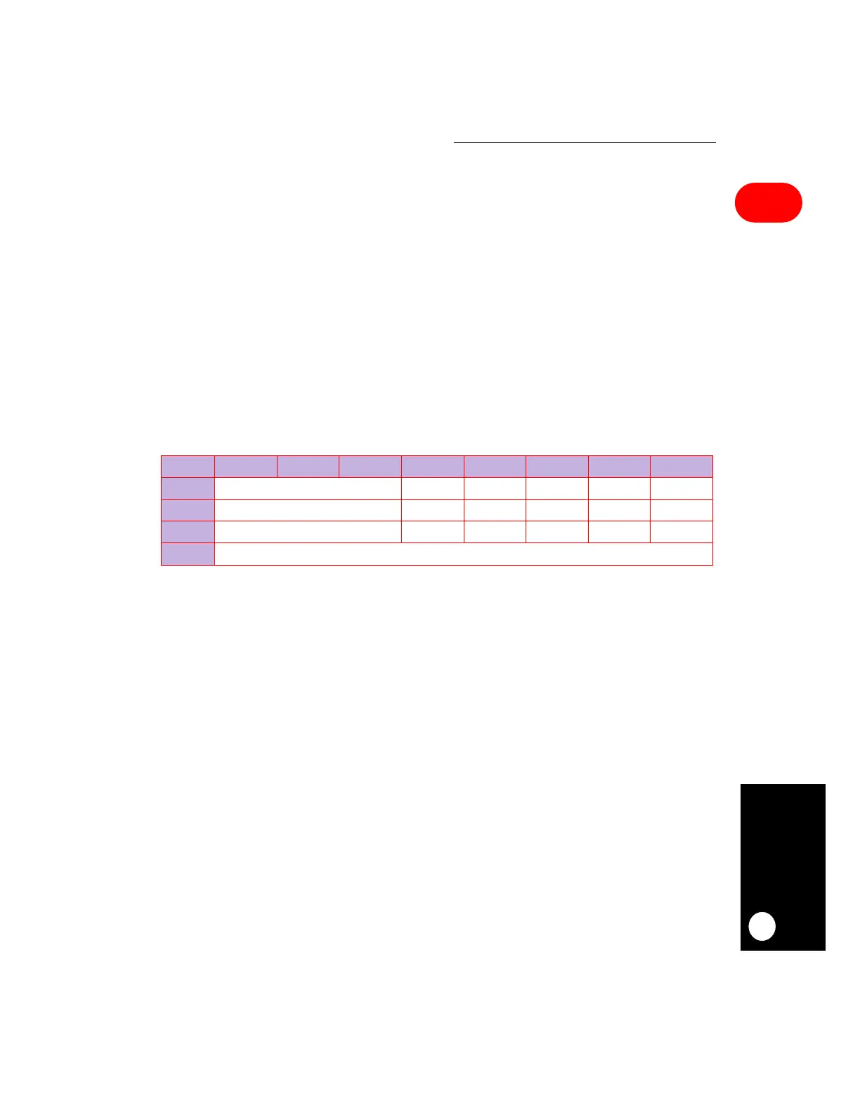
I2CER
BIT 0 1 2 3 4 5 6 7
FIELD RESERVED TXE RESERVED BSY TXB RXB
RESET 0 00000
R/W R/W R/W R/W R/W R/W R/W
ADDR (IMMR & 0xFFFF0000) + 0x870