Communication Processor Module
MOTOROLA MPC823e REFERENCE MANUAL 16-506
CPIC
COMMUNICATION
16
PROCESSOR MODULE
The interrupt vector table is the same as the CPM interrupt priority table, except for two
differences. First, the USB and SCCx vectors are fixed. They are not affected by the USB
and SCCx group mode, spread mode, or the relative priority order of the USB and SCCs.
Second, an error vector is the last entry in this table. The error vector is issued by the
communication processor module if there were no other pending interrupts or if it requested
one, but you masked it before it was serviced by the core. You must provide an error
interrupt service routine, even if it is simply an rfi instruction.
16.15.5 Programming the CPM Interrupt Controller
16.15.5.1 CPM INTERRUPT CONFIGURATION REGISTER. The 24-bit read/write CPM
interrupt configuration register (CICR) defines the request level for the CPM interrupts, the
priority between the USB and SCCs and the highest priority interrupt.
Bits 0–7 and 25–30—Reserved
These bits are reserved and must be set to 0.
SCDP—SCCd Priority Order
This field defines whether the USB or SCCs will assert a request in the SCCd priority
position.
00 = USB will assert its request in the SCCd position.
01 = SCC2 will assert its request in the SCCd position.
10 = SCC3 will assert its request in the SCCd position.
11 = Neither the USB or SCCx will assert its request in the SCCd position.
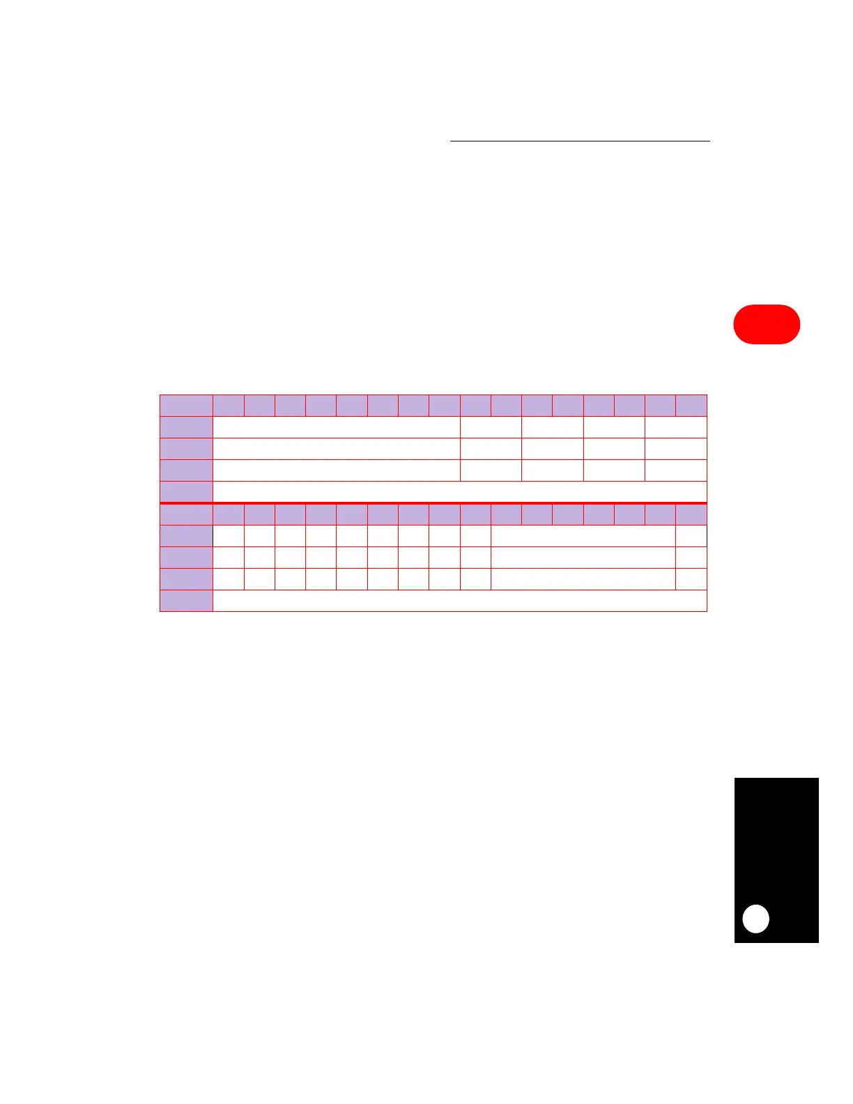
CICR
BIT 0 1 2 3 4 5 6 7 8 9 10 11 12 13 14 15
FIELD RESERVED SCDP SCCP SCBP SCAP
RESET 0 0000
R/W R/W R/W R/W R/W R/W
ADDR (IMMR & 0xFFFF0000) + 0x940
BIT 16 17 18 19 20 21 22 23 24 25 26 27 28 29 30 31
FIELD IRL0 IRL1 IRL2 HP0 HP1 HP2 HP3 HP4 IEN RESERVED SPS
RESET 000000000 0 0
R/W R/W R/W R/W R/W R/W R/W R/W R/W R/W R/W R/W
ADDR (IMMR & 0xFFFF0000) + 0x942